Page 2 - Model
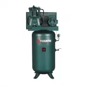
CA / CT SERIES CAP600 Page 1 of 30 REV E JULY 2014 ______________________ _____________________ Model Serial # Please have your unit’s model and serial number ready when calling for service. The model # is found on the tank decal and the serial number is located on the compressor nameplate. For Cust...
Page 3 - Table of Contents; Wiring Diagrams
CA / CT SERIES CAP600 Page 2 of 30 REV E JULY 2014 Table of Contents Read Me First Section 1 Safety Precautions ............................................................................................................ 3-4 System Diagram ...............................................................
Page 4 - READ ME FIRST; Safety Precautions; Use of FS
CA / CT SERIES CAP600 Page 3 of 30 REV E JULY 2014 READ ME FIRST Safety Precautions The owner, lessor or operator of any compressor unit manufactured by FS Curtis, Inc. is hereby warned that failure to observe all safety precautions may result in serious injury of personnel and/or damage to proper t...
Page 6 - System Diagram; Sim p l e x Un it s
CA / CT SERIES CAP600 Page 5 of 30 REV E JULY 2014 System Diagram Sim p l e x Un it s 1 2 3 4 5 6 Air Intake Air Compressor Intercooler Magnetic Starter Pressure Switch Vibration Pads withhardware mounts 1 Exact orientation of system componentsmay vary. Please see your model's generalarrangement dia...
Page 7 - D u p l e x Un it s
CA / CT SERIES CAP600 Page 6 of 30 REV E JULY 2014 D u p l e x Un it s 1 2 3 4 5 6 Air Intake Air Com pressor Intercooler Alternator Pressure Switch Vibration Isolator padswith hardware m ounts 2 Exact orientation of your system'scomponents may be different from thelayout in the figure. Please see y...
Page 8 - INSTALLATION; IMPORTANT NOTICE; Receiving; FREIGHT DAMAGE; damage is not covered by FS Curtis’s compressor warranty.
CA / CT SERIES CAP600 Page 7 of 30 REV E JULY 2014 INSTALLATION IMPORTANT NOTICE Abide by all applicable state, local and regulations when mounting and installing the compressor. Failure to do so may result in injury or death and will void the manufacturer’s warranty. Contact your local government f...
Page 9 - FREIGHT DAMAGE; Original bill of lading
CA / CT SERIES CAP600 Page 8 of 30 REV E JULY 2014 FREIGHT DAMAGE The transportation industry has adopted a modification with regard to the handling of obvious and concealed damage claims. Therefore, it is extremely important that you examine every carton and crate as soon as you receive it. If ther...
Page 10 - Installation Procedure; e compressor’s mounting pattern and prepare the surface
CA / CT SERIES CAP600 Page 9 of 30 REV E JULY 2014 Installation Procedure Step 1 – Select a proper location for installation Select a clean, dry, well lit area with a rigid floor strong enough to support the compressor and with adequate ventilation. Avoid placement of the compressor in an area that ...
Page 11 - Acceptable Mounting; Concrete Anchor Bolts
CA / CT SERIES CAP600 Page 10 of 30 REV E JULY 2014 Acceptable Mounting Unacceptable Mounting Concrete Anchor Bolts Threaded Rod or Floor Stud Steel flooring or supports (provided unit is bolted down and isolator pads are used) Skid Mounted Unanchored Bare Floor (no vibration pads) Table...
Page 12 - Recommended Installation
CA / CT SERIES CAP600 Page 11 of 30 REV E JULY 2014 Recommended Installation – Use concrete anchor bolt 1 2 3 4 5 6 7 8 Fig. (6) Recommended Installation Method 1 Mounting bolt, see Table (3) for recommended sizes 2 Flat washer, sized for bolt 3 Compressor Base 4 Vibration Isolator Pads 5 Steel Shim...
Page 13 - MOUNTING MOBILE UNITS
CA / CT SERIES CAP600 Page 12 of 30 REV E JULY 2014 Step 5 – Tighten the fasteners Incrementally tighten the mounting bolts evenly in a cross pattern. With unit running, continue incrementally tightening the mounting bolts in a crossing pattern until vibrations have been reduced to an acceptable lev...
Page 14 - Post Installation Checklist; Curtis Lube Plus
CA / CT SERIES CAP600 Page 13 of 30 REV E JULY 2014 Post Installation Checklist WARNING! Failure to perform the post installation checklist may result in mechanical failure, property damage, serious injury or even death. Steps 1 through 9 should be performed prior to connecting the unit to a power s...
Page 15 - Electrical Requirements; void the manufacturer’s warranty.
CA / CT SERIES CAP600 Page 14 of 30 REV E JULY 2014 Electrical Requirements The electrical installation of this unit should only be performed by a qualified electrician with knowledge of the National Electrical Code (N.E.C.), O.S.H.A. code and/or any local or state codes having precedence. All FS Cu...
Page 16 - Simplex Single Phase and 3 Phase; TURN OFF / TAGOUT POWER BEFORE SERVICING
CA / CT SERIES CAP600 Page 15 of 30 REV E JULY 2014 Wiring Diagrams: Simplex Single Phase and 3 Phase TURN OFF / TAGOUT POWER BEFORE SERVICING 3 2 1 5 4 Fig (7) Simplex Starter 95 96 OL PressureSwitch Power Supplyto L1 and L2 MS1 Motor Jumper T2 to L3 M L2L3 L1 OL A2 A1 T3 T2 T1 95 96 OL Pressure Sw...
Page 17 - Duplex Dual Source Alternator
CA / CT SERIES CAP600 Page 16 of 30 REV E JULY 2014 Wiring Diagrams: Duplex Dual Source Alternator TURN OFF / TAGOUT POWER BEFORE SERVICING 1 2 3 1 2 3 Fig (10) Duplex dual source alternator panel. NOTE: Unit wiring diagram is located on the inside front cover of the alternator panel. If, over time,...
Page 18 - Start Up; Pre Start Checklist; fins of the intercooler and cylinder heads.; INITIAL STARTING & OPERATION
CA / CT SERIES CAP600 Page 17 of 30 REV E JULY 2014 Start Up Pre Start Checklist WARNING! Do not proceed until the PRE-STARTING CHECKLIST and sub-section has been read and is thoroughly understood. 1. Check oil level in crankcase for proper level. 2. Drain liquid from the air receiver and moisture t...
Page 19 - For the first weeks, the compressor ne; FIRST MONTH MAINTENANCE; bolt torques subsection)
CA / CT SERIES CAP600 Page 18 of 30 REV E JULY 2014 For the first weeks, the compressor ne eds time to “break in.” The belt requires time to stretch and fit into the surface of the pulleys. The piston rings need time to seat themselves into the cylinder walls, and bearings need to wear into place. F...
Page 20 - Maintenance; Shut Down Procedure; NEVER; remove a plug to relieve the pressure.
CA / CT SERIES CAP600 Page 19 of 30 REV E JULY 2014 Maintenance Shut Down Procedure The following procedures should be followed when stopping the compressor for maintenance or service. WARNING! Never assume a compressor is safe to work on just because it is not operating. It could start at any time....
Page 21 - Maintenance Schedule
CA / CT SERIES CAP600 Page 20 of 30 REV E JULY 2014 Maintenance Schedule DESCRIPTION PART N o D A IL Y W E E K L Y MON TH L Y 3 MON TH 6 MON TH 9 MON TH 1 Y E A R Check oil level Check pressure operating point and controls Drain condensate from air receiver Manually operate the pressure relief...
Page 22 - Oil; Use Genuine; OIL CAPACITIES
CA / CT SERIES CAP600 Page 21 of 30 REV E JULY 2014 Oil OIL RECOMMENDATION Use Genuine CURTIS-LUBEPLUS Lubricants. Specially formulated for Curtis Reciprocating Air Compressors. Non-Detergent type with anti-foam, anti-rust and oxidation inhibitors. Under normal operating temperatures, use FSC-1000 I...
Page 23 - Low Oil Guard; ’s low oil guard utilizes a
CA / CT SERIES CAP600 Page 22 of 30 REV E JULY 2014 Low Oil Guard To help prevent catastrophic damage, FS Curtis provides an option for a Low Oil Guard, which prevents the unit from starting when the oil level has dropped below the low oil mark on the sight glass or dipstick, see Fig (12) for proper...
Page 24 - Bolt Torques; Challenge Air and CT Compressors; FLYWHEEL BOLTS
CA / CT SERIES CAP600 Page 23 of 30 REV E JULY 2014 Bolt Torques Challenge Air and CT Compressors E50 E57 E71 E15 Size Torque (CM-FT) Size Torque (CM-FT) Size Torque (CM-FT) Size Torque (CM-FT) Head Bolts M10-1.5 300-21.7 M10-1.5 320-23.1 M10-1.5 320-23.1 M10-1.5 320-23.1 Cylinder Case M10-1.5 280-2...
Page 25 - BELT TENSION; “throwing”; Table (8) contains deflection and tension values for CT units.
CA / CT SERIES CAP600 Page 24 of 30 REV E JULY 2014 BELT TENSION CAUTION: Over tightening the v-belt(s) will result in overloading of the motor, and/or belt and pulley failure. A loose belt will result in an unstable speed, premature belt wear, “throwing” belts and a high amp draw. To change tension...
Page 26 - aligned and adjust motor as necessary.
CA / CT SERIES CAP600 Page 25 of 30 REV E JULY 2014 Model HP Gage Deflection Average Tension Minimum Maximum 555VT6 5 1/4" 13lb 11lb 14lb 555VT8 5 1/4" 10lb 9lb 12lb 775VT8 7.5 1/4" 10lb 9lb 12lb 1075HT12 10 1/4" 8lb 7lb 10lb CT Gas 13-14 3/8" 20lb 18lb 23lb Table (8) CT Belt Ten...
Page 27 - Maintenance Parts and Rebuild Kits; CHALLENGE AIR REBUILD KITS
CA / CT SERIES CAP600 Page 26 of 30 REV E JULY 2014 Maintenance Parts and Rebuild Kits To order replacement parts for routine maintenance, please contact your local distributor. CHALLENGE AIR REBUILD KITS E57 Kit Number E50 Kit Number E71 Kit Number E15 Kit Number Oil (12 quart case) VO411-3 VO411-3...
Page 28 - Troubleshooting; Problem
CA / CT SERIES CAP600 Page 27 of 30 REV E JULY 2014 Troubleshooting Problem Cause Remedy 1 Unit won’t start Power not on Fuse blown Low voltage supplied Worn pressure switch contacts Starter overload tripped Broken / loose electrical connections Check breaker and / or disconnect Repl...
Page 29 - contact your local distributor for more assistance.
CA / CT SERIES CAP600 Page 28 of 30 REV E JULY 2014 Problem Cause Remedy 7 Low discharge pressure Manual drain not fully closed (standard model) Automatic drain not fully closed (if applicable) Clogged air filter / intake Leaks in air distribution system Clogged air distribution system W...
Page 30 - Maintenance Checklist; OIL CHANGED
CA / CT SERIES CAP600 Page 29 of 30 REV E JULY 2014 Maintenance Checklist NOTE: Please keep a record of changes and have this list available when calling technical service. OIL CHANGED Initials Date Changed Oil Low? (y/n) Initials Date Changed Oil Low? (y/n) BELT TENSIONING Initials Date Checked Mea...
Page 31 - Valve Inspected
CA / CT SERIES CAP600 Page 30 of 30 REV E JULY 2014 Maintenance Checklist NOTE: Please keep a record of changes and have this list available when calling technical service. Valve Inspected Initials Date Checked Initials Date Checked Air Leak Checks Initials Date Checked Comments Initials Date Checke...