Falcon KCH90DFFSS-CH - Manuals
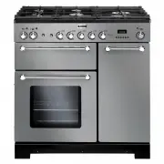
User Manual Falcon KCH90DFFSS-CH


Summary
i 1. Before You Start... 1 Personal Safety 1 Electrical Connection Safety 2 If You Smell Gas 2 Peculiar Smells 2 Cooling Fan 2 Ventilation 3Maintenance 3Grill/Glide-out Grill™ Care 5 Cooker Care 5 Cleaning 5 2. Cooker Overview 7 Hotplate Burners 7 Wok Burner 8 The Wok Cradle* 9 The Griddle* 9 The Gl...
1 Your cooker should give you many years of trouble-free cooking if installed and operated correctly. It is important that you read this section before you start.This User Guide covers a number of different models. Although some of the illustrations will look different to your particular model the f...
4 FRONT Rear stop Front bracket ArtNo.324-0001 Steam burst • DO NOT modify this appliance. This appliance is not intended to be operated by means of external timer or separated remote-control system. • If flammable materials are stored in the drawer, oven(s) or grill(s) it may explode and result in ...
Falcon Ovens Manuals
-
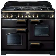 Falcon CDL110DFBL-BR
User Manual
Falcon CDL110DFBL-BR
User Manual
-
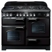 Falcon CDL110DFBL-CH
User Manual
Falcon CDL110DFBL-CH
User Manual
-
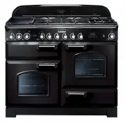 Falcon CDL110DFBL-CHLPG
User Manual
Falcon CDL110DFBL-CHLPG
User Manual
-
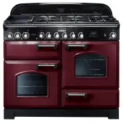
 Falcon CDL110DFCR-BR
User Manual
Falcon CDL110DFCR-BR
User Manual
-
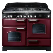
 Falcon CDL110DFCR-CH
User Manual
Falcon CDL110DFCR-CH
User Manual
-
 Falcon CDL110DFCR-CHLPG
User Manual
Falcon CDL110DFCR-CHLPG
User Manual
-
 Falcon CDL110DFCY-BR
User Manual
Falcon CDL110DFCY-BR
User Manual
-
 Falcon CDL110DFCY-CH
User Manual
Falcon CDL110DFCY-CH
User Manual
-
 Falcon CDL110DFCY-CHLPG
User Manual
Falcon CDL110DFCY-CHLPG
User Manual
-
 Falcon CDL110DFLT-CH
User Manual
Falcon CDL110DFLT-CH
User Manual
-
 Falcon CDL110DFMGBR
User Manual
Falcon CDL110DFMGBR
User Manual
-
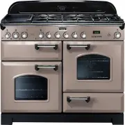
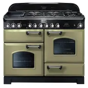
 Falcon CDL110DFOG-BR
User Manual
Falcon CDL110DFOG-BR
User Manual
-
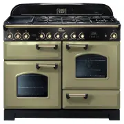
 Falcon CDL110DFOG-CH
User Manual
Falcon CDL110DFOG-CH
User Manual
-
 Falcon CDL110DFOG-CHLPG
User Manual
Falcon CDL110DFOG-CHLPG
User Manual
-
 Falcon CDL110DFRB-BR
User Manual
Falcon CDL110DFRB-BR
User Manual
-
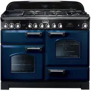 Falcon CDL110DFRB-CH
User Manual
Falcon CDL110DFRB-CH
User Manual
-
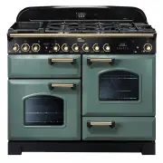
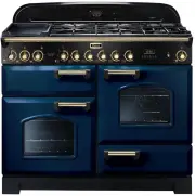
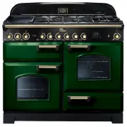 Falcon CDL110DFRG-BR
User Manual
Falcon CDL110DFRG-BR
User Manual
-
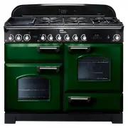 Falcon CDL110DFRG-CH
User Manual
Falcon CDL110DFRG-CH
User Manual
-
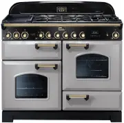 Falcon CDL110DFRP-BR
User Manual
Falcon CDL110DFRP-BR
User Manual
-
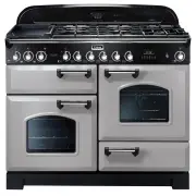 Falcon CDL110DFRP-CH
User Manual
Falcon CDL110DFRP-CH
User Manual