Falcon CLAS110EIWH-BR - Manuals
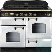
User Manual Falcon CLAS110EIWH-BR


Summary
1. Before You Start... 1 Installation and Maintenance 1 Peculiar smells 1 Ventilation 1 Personal Safety 1 Hob Care 3 Cooker Care 3 Cleaning 3 2. Cooker Overview 4 The Hob 4 The Grill / Glide-out Grill 6 The Ovens 7 The Clock 8 Accessories 12 Main Oven Light 12 3. Cooking Tips 13 Hints on Using your ...
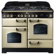
1 1. Before You Start... This User Guide covers a 3 different models. Although some of the illustrations will look different to your particular model the functions will be the same. We hope the meaning is clear. Your cooker should give you many years of trouble-free cooking if installed and operated...
3 ArtNo.090-0007 90 Ceramic: oven steam out the back Hob Care n n DO NOT use the hob surface as a cutting board. Do not leave utensils, foodstuffs or combustible items on the hob when it is not is use (e.g. tea towels, frying pans containing oil). n n DO NOT place plastic or aluminium foil, or plast...
Falcon Ovens Manuals
-
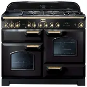 Falcon CDL110DFBL-BR
User Manual
Falcon CDL110DFBL-BR
User Manual
-
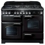 Falcon CDL110DFBL-CH
User Manual
Falcon CDL110DFBL-CH
User Manual
-
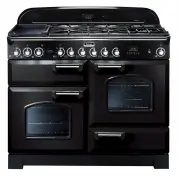 Falcon CDL110DFBL-CHLPG
User Manual
Falcon CDL110DFBL-CHLPG
User Manual
-
 Falcon CDL110DFCR-BR
User Manual
Falcon CDL110DFCR-BR
User Manual
-
 Falcon CDL110DFCR-CH
User Manual
Falcon CDL110DFCR-CH
User Manual
-
 Falcon CDL110DFCR-CHLPG
User Manual
Falcon CDL110DFCR-CHLPG
User Manual
-
 Falcon CDL110DFCY-BR
User Manual
Falcon CDL110DFCY-BR
User Manual
-
 Falcon CDL110DFCY-CH
User Manual
Falcon CDL110DFCY-CH
User Manual
-
 Falcon CDL110DFCY-CHLPG
User Manual
Falcon CDL110DFCY-CHLPG
User Manual
-
 Falcon CDL110DFLT-CH
User Manual
Falcon CDL110DFLT-CH
User Manual
-
 Falcon CDL110DFMGBR
User Manual
Falcon CDL110DFMGBR
User Manual
-
 Falcon CDL110DFOG-BR
User Manual
Falcon CDL110DFOG-BR
User Manual
-
 Falcon CDL110DFOG-CH
User Manual
Falcon CDL110DFOG-CH
User Manual
-
 Falcon CDL110DFOG-CHLPG
User Manual
Falcon CDL110DFOG-CHLPG
User Manual
-
 Falcon CDL110DFRB-BR
User Manual
Falcon CDL110DFRB-BR
User Manual
-
 Falcon CDL110DFRB-CH
User Manual
Falcon CDL110DFRB-CH
User Manual
-
 Falcon CDL110DFRG-BR
User Manual
Falcon CDL110DFRG-BR
User Manual
-
 Falcon CDL110DFRG-CH
User Manual
Falcon CDL110DFRG-CH
User Manual
-
 Falcon CDL110DFRP-BR
User Manual
Falcon CDL110DFRP-BR
User Manual
-
 Falcon CDL110DFRP-CH
User Manual
Falcon CDL110DFRP-CH
User Manual