Page 3 - SPIS TRE CI; PL
3 3 SPIS TRE CI UWAGI I SUGESTIE ............................................................................................................................................................ 64 W Ł A CIWO CI TECHNICZNE .....................................................................................
Page 4 - EN; RECOMMENDATIONS AND SUGGESTIONS; INSTALLATION
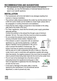
EN 4 4 RECOMMENDATIONS AND SUGGESTIONS The Instructions for Use apply to several versions of this appliance. Accordingly, you may find descriptions of individual features that do not apply to your specific appliance. INSTALLATION • The manufacturer will not be held liable for any damages resulting f...
Page 5 - USE
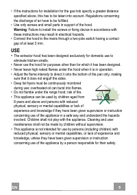
EN 5 5 • If the instructions for installation for the gas hob specify a greater distance specified above, this has to be taken into account. Regulations concerning the discharge of air have to be fulfilled. • Use only screws and small parts in support of the hood. Warning : Failure to install the sc...
Page 6 - : Accessible parts may become hot when used with cooking; MAINTENANCE; any maintenance work.
EN 6 6 • “ CAUTION : Accessible parts may become hot when used with cooking appliances.” MAINTENANCE • Switch off or unplug the appliance from the mains supply before carrying out any maintenance work. • Clean and/or replace the Filters after the specified time period (Fire hazard). • The Grease fil...
Page 7 - CHARACTERISTICS; Dimensions
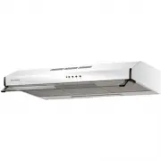
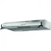
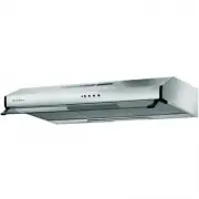
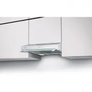
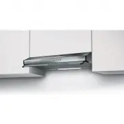
EN 7 7 CHARACTERISTICS Dimensions 11 0 145 598 / 898 /1198 500 145 145 500 260 212 275 200 100 Components Ref. Q.ty Product Components 1 1 Hood Body, complete with: Controls, Light, Blower, Filters 2 1 Chimney 8 1 Air Outlet Grill 9 1 Reducer Flange ø 150-120 mm 10 1 Shelf Frame (optional) 20 1 Wood...
Page 8 - Wall drilling and bracket fixing
EN 8 8 INSTALLATION Wall drilling and bracket fixing Hood dimension share X 60 cm 128 mm 90 cm 150 mm 120 cm 175 mm Wall marking: • Draw a vertical line on the supporting wall up to the ceiling, or as high as practical, at the centre of the area in which the hood will be installed. • Draw a horizont...
Page 9 - Flue assembly; Connections; DUCTED VERSION AIR EXHAUST SYSTEM
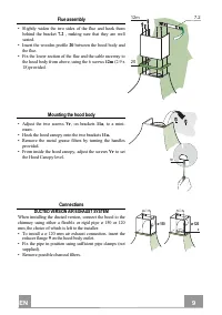
EN 9 9 Flue assembly • Slightly widen the two sides of the flue and hook them behind the bracket 7.2 , making sure that they are well seated. • Insert the wooden profile 20 between the hood body and the flue. • Fix the lower section of the flue and the cable raceway to the hood body from above, usin...
Page 10 - RECIRCULATION VERSION AIR OUTLET; Fitting Shelf frame
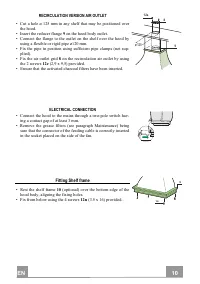
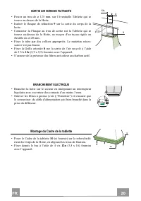
EN 1 10 RECIRCULATION VERSION AIR OUTLET • Cut a hole ø 125 mm in any shelf that may be positioned over the hood. • Insert the reducer flange 9 on the hood body outlet. • Connect the flange to the outlet on the shelf over the hood by using a flexible or rigid pipe ø120 mm. • Fix the pipe in position...
Page 12 - Grease filters; CLEANING METAL SELF- SUPPORTING GREASE FILTERS; Activated charcoal filter (Recirculation version); REPLACING THE ACTIVATED CHARCOAL FILTER
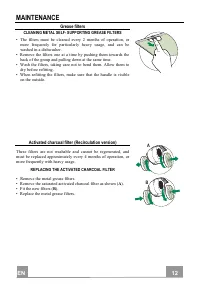
EN 1 12 MAINTENANCE Grease filters CLEANING METAL SELF- SUPPORTING GREASE FILTERS • The filters must be cleaned every 2 months of operation, or more frequently for particularly heavy usage, and can be washed in a dishwasher. • Remove the filters one at a time by pushing them towards the back of the ...
Page 13 - Lighting; LIGHT REPLACEMENT
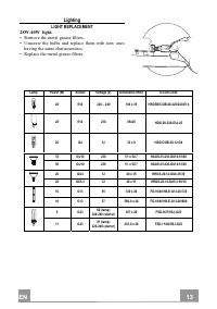
EN 1 13 Lighting LIGHT REPLACEMENT 28W-40W light. • Remove the metal grease filters. • Unscrew the bulbs and replace them with new ones having the same characteristics. • Replace the metal grease filters. Lamp Power (W) Socket Voltage (V) Dimension (mm) ILCOS Code 28 E14 220 – 240 104 x 35 HSGSB/C/U...
Page 14 - FR; CONSEILS ET SUGGESTIONS
FR 1 14 CONSEILS ET SUGGESTIONS Les instructions pour l’utilisation se réfèrent aux différents modèles de cet appareil. Par conséquent, certaines descriptions de caractéristiques particulières pourraient ne pas appartenir spécifiquement à cet appareil. INSTALLATION • En aucun cas le fabricant ne peu...
Page 15 - UTILISATION
FR 1 15 • Si les instructions d’installation du plan de cuisson à gaz spécifient une distance supérieure à celle indiquée ci-dessus, veuillez impérativement en tenir compte. Toutes les normes concernant l’évacuation de l’air doivent être respectées. • Utiliser exclusivement des vis et des petites pi...
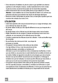
Page 16 - les parties accessibles peuvent devenir très chaudes durant; ENTRETIEN; débrancher l’appareil du secteur.
FR 1 16 • ATTENTION : les parties accessibles peuvent devenir très chaudes durant l’utilisation des appareils de cuisson. ENTRETIEN • Avant d’effectuer toute opération de nettoyage et d’entretien, éteindre ou débrancher l’appareil du secteur. • Nettoyer et/ou remplacer les filtres après le délai ind...
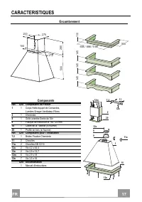
Page 17 - CARACTERISTIQUES; Encombrement
FR 1 17 CARACTERISTIQUES Encombrement 11 0 145 598 / 898 /1198 500 145 145 500 260 212 275 200 100 Composants Réf. Q.té Composants de Produit 1 1 Corps Hotte équipé de:Comandes, Lumière,Groupe Ventilateur,Filtres 2 1 Cheminée 8 1 Grille orientée Sortie de l’Air 9 1 Flasque de Réduction ø 150-120 mm ...
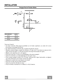
Page 18 - Perçage Paroi et Fixation Brides
FR 1 18 INSTALLATION Perçage Paroi et Fixation Brides Hotte dimension Quota X 60 cm 128 mm 90 cm 150 mm 120 cm 175 mm Tracer sur la paroi: • une ligne verticale allant jusqu’au plafond ou à la limite supérieure, au centre de la zone prévue pour le montage de la hotte; • une ligne horizontale à 650 m...
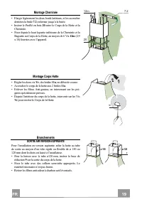
Page 19 - Montage Cheminée; Branchements; SORTIE AIR VERSION ASPIRANTE
FR 1 19 Montage Cheminée • Elargir légèrement les deux bords latériaux, et les accrocher derrières la bride 7.2 ; refermer jusqu’à la butée. • Insérer le Profilé en bois 20 entre le Corps de la Hotte et la Cheminée. • Fixer depuis le haut la partie inférieure de la Cheminée et la Baguette au Corps d...
Page 20 - SORTIE AIR VERSION FILTRANTE; Montage du Cadre de la tablette
FR 2 20 SORTIE AIR VERSION FILTRANTE • Percer un trou de ø 125 mm. sur l’éventuelle Tablette qui se trouve au-dessus de la Hotte. • Insérer le flasque de réduction 9 sur la sortie du corps de la hotte. • Connecter la Flasque au trou de sortie sur la Tablette qui se trouve au-dessus de la Hotte, au m...
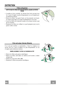
Page 22 - Filtres anti-graisse; NETTOYAGE FILTRES ANTI-GRAISSE METALLIQUES AUTOPOR-
FR 2 22 ENTRETIEN Filtres anti-graisse NETTOYAGE FILTRES ANTI-GRAISSE METALLIQUES AUTOPOR- TEURS • Lavables au lave-vaisselle, ils doivent être lavés environ tous les 2 mois d’emploi ou plus fréquemment en cas d’emploi par-ticulièrement intense. • Retirer les filtres l’un aprés l’autre, en les pouss...
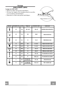
Page 23 - Eclairage; REMPLACEMENT LAMPES
FR 2 23 Eclairage REMPLACEMENT LAMPES Lampes de 28W-40W • Retirer les filtres anti-graisse métalliques. • Dévisser les lampes et les remplacer par de nouvelles avec les mêmes caractéristiques. • Remonter les filtres anti-graisse métalliques. Ampoule Absorption (W) Culot Voltage (V) Dimensions (mm) C...
Page 24 - DE; EMPFEHLUNGEN UND HINWEISE
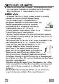
DE 2 24 EMPFEHLUNGEN UND HINWEISE Diese Gebrauchsanleitungen beziehen sich auf die verschiedenen Modelle der Abzugshaube. Darum kann es möglich sein, dass die Beschreibung bestimmter Merkmale für das vorliegende Gerät nicht zutrifft. INSTALLATION • Der Hersteller haftet nicht für etwaige Schäden, di...
Page 25 - von mindestens 3 mm an das Netz anschließen.; GEBRAUCH; • Fritteusen müssen während des Gebrauchs ständig
DE 2 25 • Falls die Montageanweisungen für die gasbetriebene Kochmulde einen größeren Abstand vorschreiben, als der oben angegebene, muss diese Vorgabe befolgt werden. Es sind sämtliche Abluftvorschriften zu beachten. • Nur für die Abzugshaube geeignete Schrauben und Kleinteile verwenden. Achtung : ...
Page 26 - WARTUNG
DE 2 26 • ACHTUNG: Die zugänglichen Teile können während des Gebrauchs der Kochgeräte sehr heiß werden. WARTUNG • Vor Reinigungs- oder Wartungsarbeiten am Gerät, muss dieses ausgeschaltet und spannungslos gemacht werden. • Die Filter stets nach den angegebenen Intervallen reinigen oder auswechseln (...
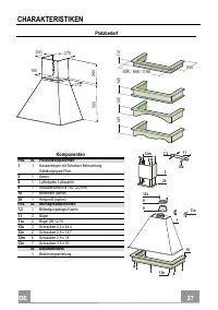
Page 27 - CHARAKTERISTIKEN; Platzbedarf
DE 2 27 CHARAKTERISTIKEN Platzbedarf 11 0 145 598 / 898 /1198 500 145 145 500 260 212 275 200 100 Komponenten Pos. St. Produktkomponenten 1 1 Haubenkörper mit Schaltern,Beleuchtung, Gebläsegruppe,Filter 2 1 Kamin 8 1 Luftleitgitter Luftaustritt 9 1 Reduzierflansch ø 150-120 mm 10 1 Bordleiste (optio...
Page 28 - MONTAGE
DE 2 28 MONTAGE Bohren der Befestigungslöcher und Fixieren der Befestigungsbügel Maß der Haube Breite X 60 cm 128 mm 90 cm 150 mm 120 cm 175 mm Nachstehende Linien an die Wand zeichnen: • eine vertikale Linie bis zur Decke oder oberen Begrenzung, und zwar in der Mitte des Be- reiches, in dem die Hau...
Page 29 - Kaminmontage; Anschluss im Abluftbetrieb
DE 2 29 Kaminmontage • Die beiden seitlichen Schenkel leicht auseinander- biegen, hinter dem Bügel 7.2 einhängen und bis zum Anschlag wieder schließen. • Das Holzprofil 20 zwischen Haubenkörper und Ka- min einfügen. • Von der Oberseite her den Unterteil des Kamins und die Kabelabdeckung zum Haubenkö...
Page 30 - Anschluss im Umluftbetrieb; Montage der Bordleiste
DE 3 30 Anschluss im Umluftbetrieb • In das eventuell über der Haube vorhandene Bord ein Loch ø 125 mm bohren. • Den Reduzierflansch 9 am Haubenaustritt anbringen. • Den Flansch beim Luftaustritt am Bord oberhalb der Haube mittels Rohr oder Schlauch ø120 mm anschließen. • Das Rohr mit geeigneten Roh...
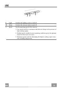
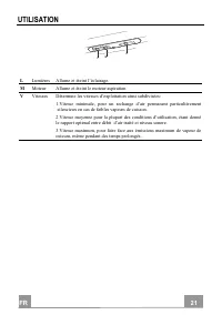
Page 31 - BEDIENUNG
DE 3 31 BEDIENUNG 1 1 0 1 0 2 3 L M V L Beleucht Schaltet die Beleuchtung ein und aus M Motor Schaltet den Gebläsemotor ein und aus V Geschw. Steuert folgende Geschwindigkeitsstufen: 1.geringste Gebläsestufe, diese Stufe ist für einen ständigen und besonders leisen Luftaustausch bei geringer Kochdun...
Page 32 - Fettfilter; SELBSTTRAGENDER METALLFETTFILTER REINIGUNG
DE 3 32 WARTUNG Fettfilter SELBSTTRAGENDER METALLFETTFILTER REINIGUNG • Sie müssen nach 2-monatigem Betrieb bzw. bei starkem Ein- satz auch häufiger gereinigt werden, was im Geschirrspüler möglich ist. • Die Filter nacheinander aushaken, indem sie auf die Rückseite der Gruppe geschoben und gleichzei...
Page 33 - Beleuchtung; AUSWECHSELN DER LAMPEN
DE 3 33 Beleuchtung AUSWECHSELN DER LAMPEN Lampen 28W-40W • Die Metallfettfilter entfernen. • Die Lampen ausschrauben und durch gleichwertige ersetzen. • Die Metallfettfilter wieder montieren. Lampe Leistung (W) Fassung Spannung (V) Größe (mm) ILCOS-Code 28 E14 220 – 240 104 x 35 HSGSB/C/UB-28-220/2...
Page 34 - ES; CONSEJOS Y SUGERENCIAS; INSTALACIÓN
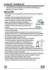
ES 3 34 CONSEJOS Y SUGERENCIAS Las instrucciones de uso se aplican a varios modelos de este aparato. Por lo tanto, usted puede encontrar descripciones de características individuales que no pertenecen a su aparato en concreto. INSTALACIÓN • El fabricante no se hace responsable de los daños provocado...
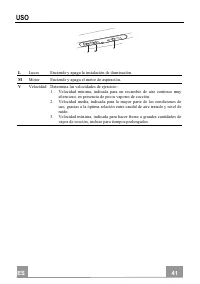
Page 35 - USO
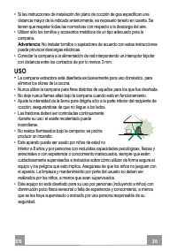
ES 3 35 • Si las instrucciones de instalación del plano de cocción de gas especifican una distancia mayor de la indicada anteriormente, es necesario tenerlo en cuenta. Se tienen que respetar todas las normativas con respecto a la descarga del aire. • Utilizar sólo los tornillos y accesorios metálico...
Page 36 - : las partes accesibles pueden calentarse mucho durante el uso de; MANTENIMIENTO; limpieza o mantenimiento.
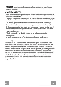
ES 3 36 • ATENCIÓN : las partes accesibles pueden calentarse mucho durante el uso de aparatos de cocción. MANTENIMIENTO • Apague o desconecte el aparato de la red eléctrica antes de cualquier operación de limpieza o mantenimiento. • Limpie y/o reemplace los filtros después del período de tiempo espe...
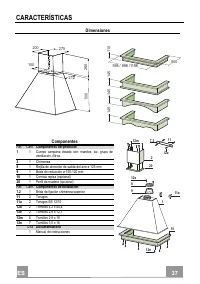
Page 37 - CARACTERÍSTICAS; Dimensiones
ES 3 37 CARACTERÍSTICAS Dimensiones 11 0 145 598 / 898 /1198 500 145 145 500 260 212 275 200 100 Componentes Ref. Cant. Componentes del producto 1 1 Cuerpo campana dotado con: mandos, luz, grupo de ventilación, filtros. 2 1 Chimenea 8 1 Rejilla de dirección de salida del aire ø 125 mm 9 1 Brida de r...
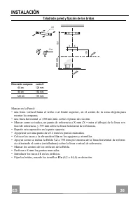
Page 38 - Taladrado pared y fijación de las bridas
ES 3 38 INSTALACIÓN Taladrado pared y fijación de las bridas Dimensión campana cuota X 60 cm 128 mm 90 cm 150 mm 120 cm 175 mm Marcar en la Pared: • una linea vertical hasta el techo o al límite superior, en el centro de la zona elegida para montar la campana; • una linea horizontal a: 650 mm mín. s...
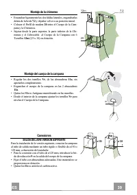
Page 39 - Montaje de la chimenea; Conexiones; SALIDA DEL AIRE VERSIÓN ASPIRANTE
ES 3 39 Montaje de la chimenea • Ensanchar ligeramente las dos faldas laterales, engancharlas detrás de la brida 7.2 y dejarlas volver a su posición inicial. • Colocar el Perfil de madera 20 entre el Cuerpo de la Cam- pana y la Chimenea. • Sujetar desde la parte superior, la parte inferior de la Chi...
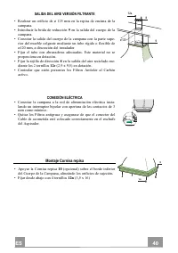
Page 40 - SALIDA DEL AIRE VERSIÓN FILTRANTE; Montaje Cornisa repisa
ES 4 40 SALIDA DEL AIRE VERSIÓN FILTRANTE • Realizar un orificio de ø 125 mm en la repisa de encima de la campana. • Introducir la brida de reducción 9 en la salida del cuerpo de la campana. • Conectar la salida del cuerpo de la campana con la parte supe- rior del mueble colgante mediante un tubo rí...
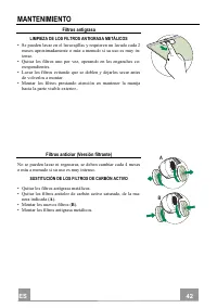
Page 42 - Filtros antigrasa; LIMPIEZA DE LOS FILTROS ANTIGRASA METÁLICOS
ES 4 42 MANTENIMIENTO Filtros antigrasa LIMPIEZA DE LOS FILTROS ANTIGRASA METÁLICOS • Se pueden lavar en el lavavajillas y requieren un lavado cada 2 meses aproximadamente o más a menudo si su uso es muy in-tenso. • Quitar los filtros uno por vez, operando en los enganches co- rrespondientes. • Lava...
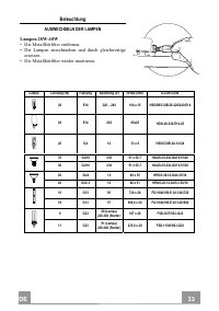
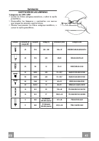
Page 43 - Iluminación; SUSTITUCIÓN DE LAS LÁMPARAS
ES 4 43 Iluminación SUSTITUCIÓN DE LAS LÁMPARAS Lámparas de 28W-40W • Quitar los filtros antigrasa metálicos, o abrir la rejilla portafiltros. • Destornillar las lámparas y sustituirlas con nuevas que tengan las mismas características. • Montar nuevamente los filtros antigrasa metálicos, o cerrar la...
Page 44 - GR
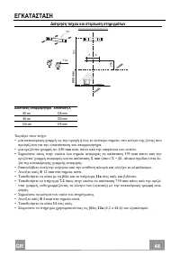
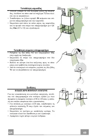
GR 4 44 . , . • . • 650 mm ( . ). • . • , . 120 mm. . • ( . . , .). • ( . . ), . . , 0,04 mbar . • ( ). • , , . 2°
Page 47 - gjk ji
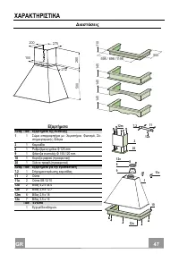
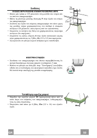
GR 4 47 gjk ji 11 0 145 598 / 898 /1198 500 145 145 500 260 212 275 200 100 . . 1 1 : , , - , 2 1 8 1 125 mm 9 1 150-120 mm 10 1 ( ) 20 1 ( ) . . 7.2 1 11 2 11a 2 SB 12/10 12a 2 4,2 x 44,4 12e 2 2,9 x 12,7 12m 6 2,9 x 18 12n 7 3,5 x 16 . 1 1 2 12m 20 7.2 12n 10 11 12a 12e 8 9 11a
Page 53 - g ヾk i
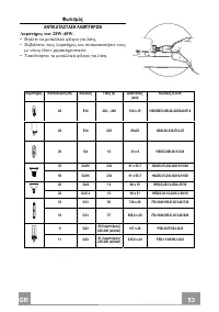
GR 5 53 g ヾk i k 28W-40W. • . • . • . (W) (V) (mm) ILCOS 28 E14 220 – 240 104 x 35 HSGSB/C/UB-28-220/240-E14 28 E14 230 85x25 HDG-28-230-E14-25 20 G4 12 33 x 9 HSG/C/UB-20-12-G4 35 GU10 230 51 x 50,7 HAGS-35-230-GU10-51/40 50 GU10 230 51 x 50,7 HAGS-35-230-GU10-51/20 20 GU4 12 40 x 35 HRGS-20-12-GU4...
Page 54 - RU
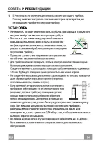
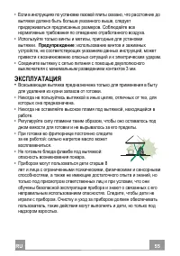
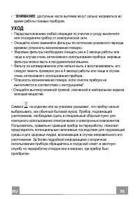
RU 5 54 . , . • , . • 650 ( ; . , ). • , . • I , . 120 . . • , , ( , , .). • , ( , ), . . , , 0,04 , . • , . 2°
Page 64 - UWAGI I SUGESTIE; MONTA
PL 6 64 UWAGI I SUGESTIE Instrukcja obs ł ugi dotyczy ró nych modeli niniejszego urz dzenia. Dlatego te w niektórych jej miejscach mo na znale Ε opisy, które nie dotycz tego konkretnego urz dzenia. MONTA • Producent nie ponosi odpowiedzialno ci za ewentualne szkody spowodowane przez nieprawid ł ow i...
Page 65 - U YTKOWANIE
PL 6 65 • Je li instrukcja instalacji kuchenki gazowej wskazuje na potrzeb zastosowana wi kszej odleg ł o ci ni podana powy ej, nale y to wzi Ε pod uwag . Nale y przestrzega Ε wszystkich norm dotycz cych odprowadzania powietrza. • U ywa Ε wy ł cznie rub oraz osprz tu typu odpowiedniego dla danego ok...
Page 66 - KONSERWACJA
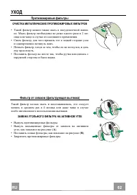
PL 6 66 • „ UWAGA : cz ci zewn trzne mog sta Ε si bardzo gor ce, je eli u ywane s razem z urz dzeniami przeznaczonymi do gotowania”. KONSERWACJA • Wy ł czy Ε urz dzenie lub od ł czy Ε je od ród ł a zasilania elektrycznego przed przyst pieniem do wszelkich prac zwi zanych z czyszczeniem i konserwacj ...
Page 67 - A CIWO CI TECHNICZNE; Wymiary
PL 6 67 W Ł A CIWO CI TECHNICZNE Wymiary 11 0 145 598 / 898 /1198 500 145 145 500 260 212 275 200 100 Cz ci L.p. Ilo Ε Cz ci okapu 1 1 Korpus okapu razem z: W ł cznikami, O wietleniem, Dmuchaw , Filtrami 2 1 Os ł ona przewodu kominowego: 8 1 Kratka wentylacyjna 9 1 Ko ł nierz redukuj cy o rednicy 15...
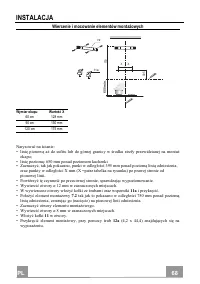
Page 68 - INSTALACJA; Wiercenie i mocowanie elementów monta owych
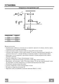
PL 6 68 INSTALACJA Wiercenie i mocowanie elementów monta owych Wymiar okapu Warto Ε X 60 cm 128 mm 90 cm 150 mm 120 cm 175 mm Narysowa Ε na cianie: • lini pionow a do sufitu lub do górnej granicy w rodku strefy przewidzianej na monta okapu; • lini poziom : 650 mm ponad poziomem kuchenki. • Zaznaczy ...
Page 69 - Pod; WYLOT POWIETRZA WERSJA Z WYCI GIEM
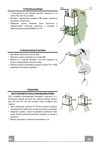
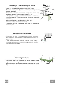
Monta os ł ony przewodu kominowego • Nale y delikatnie odgi Ε boki cz ci os ł ony i zacze- pi Ε je o wspornik 7.2 , upewniaj c si , e zosta ł y do- brze osadzone. • Umie ci Ε profil drewniany 20 mi dzy korpusem okapu i os ł on przewodu kominowego. • Przymocowa Ε os ł on przy u yciu 6 wkr tów 12m (2,...
Page 70 - PRACA W TRYBIE RECYRKULACJI; Monta pó
PL 7 70 PRACA W TRYBIE RECYRKULACJI • Je eli ponad okapem znajduje si pó ł ka nale y wyci Ε w niej otwór ø 125 mm. • Za ł o y Ε ko ł nierz redukuj cy 9 na wylot powietrza. • Po ł czy Ε ko ł nierz redukuj cy z wylotem powietrza zamoco- wanym w pó ł ce za pomoc gi tkiej lub sztywnej rury ø 120 mm. • Z...
Page 71 - Panel sterowania
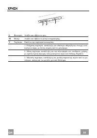
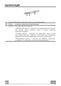
PL 7 71 U YTKOWANIE 1 1 0 1 0 2 3 L M V Panel sterowania L O wietlenie W ł cza i wy ł cza o wietlenie M Silnik W ł cza i wy ł cza silnik okapu V Pr dko Ε Pozwala na wybranie pr dko ci pracy wentylatora 1 .Pr dko Ε niska, przewidziana do sta ł ej i cichej wentylacji kuchni przy niewielkiej ilo ci opa...
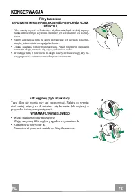
Page 72 - Filtry t; CZYSZCZENIE METALOWYCH, SAMONO NYCH FILTRÓW T
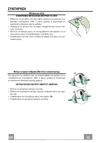
PL 7 72 KONSERWACJA Filtry t ł uszczowe CZYSZCZENIE METALOWYCH, SAMONO NYCH FILTRÓW T Ł USZ- CZOWYCH • Filtry nale y czy ci Ε co 2 miesi ce u ytkowania, b d cz ciej w przy- padku intensywnego u ywania. Mo liwe jest czyszczenie ich w zmy-warce. • Nale y zdejmowa Ε filtry po kolei, przesuwaj c ich uch...
Page 73 - O wietlenie; WYMIANA ARÓWEK
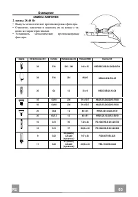
PL 7 73 O wietlenie WYMIANA ARÓWEK b arówki 28W-40W • Wyj Ε metalowe filtry t ł uszczowe. • Wykr ci Ε uszkodzon arówk i wymieni Ε na now o takich samych parametrach. • Zamontowa Ε ponownie metalowe filtry t ł uszczowe. Typ arówki Moc (W) Mocowanie Napi cie (V) Wymiary (mm) Kod ILCOS 28 E14 220 – 240...

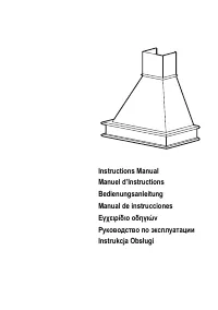


 Faber 110.0338.674
User Manual
Faber 110.0338.674
User Manual
 Faber 110.0338.675
User Manual
Faber 110.0338.675
User Manual
 Faber 110.0389.223
User Manual
Faber 110.0389.223
User Manual
 Faber 741 BASE BK A60
User Manual
Faber 741 BASE BK A60
User Manual
 Faber 741 BASE BK A60 EXP
User Manual
Faber 741 BASE BK A60 EXP
User Manual
 Faber 741 BASE W A50
User Manual
Faber 741 BASE W A50
User Manual
 Faber 741 BASE W A50 FB EXP
User Manual
Faber 741 BASE W A50 FB EXP
User Manual
 Faber 741 BASE W A60
User Manual
Faber 741 BASE W A60
User Manual
 Faber 741 BASE X A50
User Manual
Faber 741 BASE X A50
User Manual
 Faber 741 BASE X A50 FB EXP
User Manual
Faber 741 BASE X A50 FB EXP
User Manual
 Faber 741 BASE X A60
User Manual
Faber 741 BASE X A60
User Manual
 Faber 741 BASE X A60 FB EXP
User Manual
Faber 741 BASE X A60 FB EXP
User Manual
 Faber 741 PB W A50
User Manual
Faber 741 PB W A50
User Manual
 Faber 741 PB W A50 300.0557.512
User Manual
Faber 741 PB W A50 300.0557.512
User Manual
 Faber 741 PB W A60
User Manual
Faber 741 PB W A60
User Manual
 Faber 741 PB W A60 300.0557.513
User Manual
Faber 741 PB W A60 300.0557.513
User Manual
 Faber 741 PB X A50
User Manual
Faber 741 PB X A50
User Manual
 Faber 741 PB X A50 300.0557.514
User Manual
Faber 741 PB X A50 300.0557.514
User Manual
 Faber 741 PB X A60
User Manual
Faber 741 PB X A60
User Manual
 Faber 741 PB X A60 300.0557.515
User Manual
Faber 741 PB X A60 300.0557.515
User Manual