Faber LUFT X A90 - Manuals
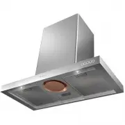
User Manual Faber LUFT X A90
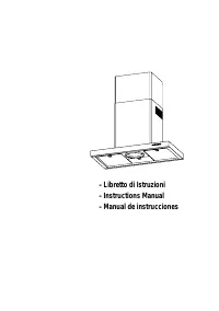


Summary
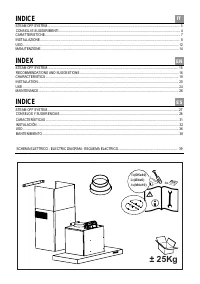
± 2 5 Kg 4 x ( M 4 x 1 0 ) 2 x ( Ø 4 x 6 ) 7 x ( Ø5x40 ) 4x INDICE STEAM OFF SYSTEM .................................................. ............. ............................................................................................ 3 CARATTERISTICHE............................................
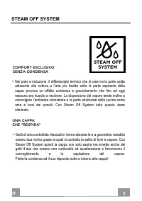
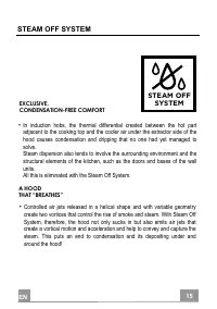
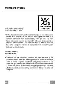
IT 3 3 STEAM OFF SYSTEM • Nei piani a induzione, il differenziale termico che si crea tra la parte calda adiacente alla cottura e l’aria più fredda sotto la parte aspirante della cappa provoca un effetto condensa e gocciolamento che fino ad oggi nessuno era riuscito a risolvere. La dispersione del v...
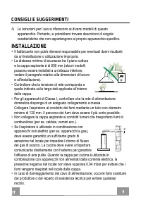
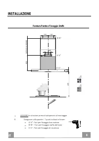
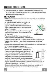
IT CONSIGLI E SUGGERIMENTI Le Istruzioni per l’uso si riferiscono ai diversi modelli di questo apparecchio. Pertanto, si potrebbero trovare descrizioni di singole caratteristiche che non appartengono al proprio apparecchio specifico. INSTALLAZIONE • Il fabbricante non potrà ritenersi responsabile pe...
Faber Range Hoods Manuals
-
 Faber 110.0338.674
User Manual
Faber 110.0338.674
User Manual
-
 Faber 110.0338.675
User Manual
Faber 110.0338.675
User Manual
-
 Faber 110.0389.223
User Manual
Faber 110.0389.223
User Manual
-
 Faber 741 BASE BK A60
User Manual
Faber 741 BASE BK A60
User Manual
-
 Faber 741 BASE BK A60 EXP
User Manual
Faber 741 BASE BK A60 EXP
User Manual
-
 Faber 741 BASE W A50
User Manual
Faber 741 BASE W A50
User Manual
-
 Faber 741 BASE W A50 FB EXP
User Manual
Faber 741 BASE W A50 FB EXP
User Manual
-
 Faber 741 BASE W A60
User Manual
Faber 741 BASE W A60
User Manual
-
 Faber 741 BASE X A50
User Manual
Faber 741 BASE X A50
User Manual
-
 Faber 741 BASE X A50 FB EXP
User Manual
Faber 741 BASE X A50 FB EXP
User Manual
-
 Faber 741 BASE X A60
User Manual
Faber 741 BASE X A60
User Manual
-
 Faber 741 BASE X A60 FB EXP
User Manual
Faber 741 BASE X A60 FB EXP
User Manual
-
 Faber 741 PB W A50
User Manual
Faber 741 PB W A50
User Manual
-
 Faber 741 PB W A50 300.0557.512
User Manual
Faber 741 PB W A50 300.0557.512
User Manual
-
 Faber 741 PB W A60
User Manual
Faber 741 PB W A60
User Manual
-
 Faber 741 PB W A60 300.0557.513
User Manual
Faber 741 PB W A60 300.0557.513
User Manual
-
 Faber 741 PB X A50
User Manual
Faber 741 PB X A50
User Manual
-
 Faber 741 PB X A50 300.0557.514
User Manual
Faber 741 PB X A50 300.0557.514
User Manual
-
 Faber 741 PB X A60
User Manual
Faber 741 PB X A60
User Manual
-
 Faber 741 PB X A60 300.0557.515
User Manual
Faber 741 PB X A60 300.0557.515
User Manual