Page 3 - ASSISTANCE AND SPARE PARTS; the best functioning results.; IMPORTANT NOTICE; surface near by the appliance for easy reference.; DOMESTIC USE ONLY; CONTENTS
3 461308092_003 10/2013 ASSISTANCE AND SPARE PARTS the best functioning results. Any subsequent repairs or adjustments that may be necessary must be done with the maximum of care and attention by authorised personnel. For this reason we recommend you always contact us (refer below), specifying the b...
Page 4 - to make all the modiications to its
4 IMPORTANT NOTES AND PRECAUTIONS FOR USE You have purchased one of our products for which we thank you. We are conident that this new appliance, modern, functional and practical, made with top quality materials, will meet all your demands. This new appliance is easy to use but before installing and...
Page 6 - Do not; • Not suitable for installation or; IMPORTANT NOTES AND PRECAUTIONS FOR USE
6 • The appliance is not intended to be operated by means of an external timer or separate remote-control system • Ensure that the appliance is switched off before replacing the lamp to avoid the possibility of electric shock.. • The cookers can be equipped with a small compartment under the oven th...
Page 7 - PRESENTATION; Our c; Supply and quantities vary from model; . Ensure shelf is located with; DESCRIPTION OF THE APPLIANCE
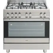
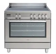
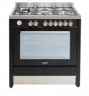
7 461308092_003 10/2013 1 2 PRESENTATION Our c ooker is i tted with a fully gas hotplate. Each knob on the front panel has a diagram printed above it showing to which burner it refers. The combination of the different sized burners offers the possibility of various types of cooking. Our cookers are ...
Page 8 - DESCRIPTION OF THE CONTROLS; By rotating the knob in an anticlockwise direction, the; OVEN FAN BUTTON; INSTRUCTIONS FOR THE USER; we will ind the following symbols.
8 DESCRIPTION OF THE CONTROLS HOB GAS BURNER KNOB (A) By rotating the knob in an anticlockwise direction, the following symbols appear: 0 = Closed position = “Full on” position = “Reduced rate or Low” position GAS OVEN/ELECTRIC GRILL THERMOSTAT KNOB (B) By rotating the knob in an anticlockwise direc...
Page 9 - HOB: GENERAL NOTES ON SAFETY; AUTOMATIC ELECTRIC IGNITION OF COOKTOP; OPTIMUM USE OF COOKTOP BURNERS; Low position”; ABNORMAL OPERATION
9 461308092_003 10/2013 HOB: GENERAL NOTES ON SAFETY • When using the burners, do not leave the appliance unsupervised. Ensure that children and the inirm do not play with the appliance. In particular, make sure that pan handles are positioned correctly and supervise the cooking of foods which use o...
Page 10 - OVEN: GENERAL SAFETY INSTRUCTIONS
10 6 5 7 8 INSTRUCTIONS FOR THE USER OVEN: GENERAL SAFETY INSTRUCTIONS • Do not leave the oven unsupervised during use. Ensure that children and the inirm do not play with the appliance. • Do not spray aerosols in the vicinity of this appliance while it is operating. • Always grip the centre of the ...
Page 11 - HOW TO USE GAS OVEN; The oven burner can be itted with a safety
11 461308092_003 10/2013 INSTRUCTIONS FOR THE USER HOW TO USE GAS OVEN The oven burner can be itted with a safety thermocouple so, once the burner has been lit, keep the knob pressed for about 15 seconds. If, at the end of this time, the burner fails to light, release the knob and wait at least 1 mi...
Page 12 - TIME AND TEMPERATURE CHART; • Remenber to remove grill tray from oven before baking in oven.; RETAIN THIS CHART FOR EASY REFERENCE; size of the meat and the other foods to be cooked at the same time.
12 TIME AND TEMPERATURE CHART The above table gives guidelines for cooking a range of different foods, individual food, or personal preferences may slightly vary the oven position, temperature and cooking time from those suggested. Please note that: • All cooking temperatures stated refer to a prehe...
Page 13 - correctly itted to protect the controls and facia
13 461308092_003 10/2013 10 AUTOMATIC ELECTRIC IGNITION OF THE GRILL BURNER Automatic ignition is achieved by irstly, fully opening the oven door and then pushing and turning the gas control knob (B) clockwise to the grill setting, then depress the knob. Automatically the ignition spark shoots. Cont...
Page 14 - USEFUL COOKING TIPS
14 INSTRUCTIONS FOR THE USER USEFUL COOKING TIPS Cakes and bread: • Heat the oven for at least 15 minutes before you start cooking bread or cakes. • Do not open the door during baking because the cold air would stop the yeast from rising. • When the cake is cooked turn the oven off and leave it in f...
Page 15 - itted on appliance, but in this way, pay attention; CLEANING AND MAINTENANCE
15 461308092_003 10/2013 INSTRUCTIONS FOR THE USER 11 NEVER use sponges or abrasive products, and aromatic or aliphatic solvents to remove stains or adhesives on the painted or stainless steel surfaces. OVEN CAVITY Do not spray or wash the thermostat bulb with acid based products (check the product ...
Page 17 - INSTRUCTIONS FOR THE INSTALLER; TECHNICAL INFORMATION; VENTILATION
17 461308092_003 10/2013 14 INSTRUCTIONS FOR THE INSTALLER TECHNICAL INFORMATION The installations, conversions and maintenance operations listed in this part must only be carried out by authorised personnel. The manufacturer cannot be held responsible for any damage to persons or property resulting...
Page 18 - LEVELLING THE COOKER; This can be done by means; Backguard; with this accessory, leave the factory with this part; M A I N T E N A N C E S C H E D U L E
18 15 16 A INSTRUCTIONS FOR THE INSTALLER LEVELLING THE COOKER • Adjustable feet, to be itted to the appliance, which allow the height of the cooker to be aligned with other kitchen furniture This can be done by means of the terminal part of the leg themselves (ig. 15) • Backguard . The cookers whic...
Page 19 - Assembly instructions
19 461308092_003 10/2013 INSTRUCTIONS FOR THE INSTALLER SECURING THE COOKER TO WALL (ig. P) Note:- The installation of the chain provided is for safety reasons, it must be installed as indicated below. To prevent the cooker tipping forwards in the event of children standing on the oven door o...
Page 20 - INSTRUCTION FOR STABILIZING THE COOKER; Fix the bracket on the cooker.; WARNING
20 INSTRUCTION FOR STABILIZING THE COOKER Fix the bracket on the cooker. One for each side. Align the cooker with the surrounding cupboard. Measure the distance from the loor and from the ixing point of the bracket.( X ) WARNING : In order to prevent the cooker tipping forwards in the event of child...
Page 21 - Hose Restraint Chain; Mark it the same dis
21 461308092_003 10/2013 Drill two holes in the wall for each bracket according to the ig. 2 and ix the bracket. Hose Restraint Chain The installer must it a chain, no more than 80% of the hose length to ensure that there is no strain on the hose when the cooker is pulled forward. Attach one end of ...
Page 22 - GAS CONNECTION; Installation for Natural gas; Installation using lexible connection
22 GAS CONNECTION This appliance shall be installed only by authorised personnel and in accordance with the manufacturer’s installation instructions, local gas itting regulations, municipal building codes, water supply regulations, electrical wiring regulations, AS 5601 - Gas Installations and any o...
Page 23 - ELECTRICAL CONNECTION
23 461308092_003 10/2013 ELECTRICAL CONNECTION The electrical connection must be carried out in accordance with the current standards and laws in force and by an authorised electrician. • Warning this appliance must be earthed.• Connection to the electricity supply must be made by an authorised elec...
Page 24 - GAS CONVERSIONS
24 Hot Plate Ignition Failure • Check alignment of burner holes to electrode. • Check aeration sleeve for adjustment for gas type, location and ambient conditions. • No spark, check ignition box failure or power supply. Before Leaving • Check all connections for gas leaks with soap and water. DO NOT...
Page 25 - MAINTENANCE; REPLACING THE TAPS AND THERMOSTAT; Proceed in the following way when replacing a tap or
25 461308092_003 10/2013 INSTRUCTIONS FOR THE INSTALLER MAINTENANCE Prior to any maintenance work or changing parts, disconnect the appliance from the gas and electricity power sources. Servicing must only be carried out by authorised personnel. REPLACING THE TAPS AND THERMOSTAT Proceed in the follo...
Page 26 - TECHNICAL FEATURES; BURNER DISPOSITION; NOMINAL DATA; TECHNICAL DATA; GAS
26 TECHNICAL FEATURES BURNER DISPOSITION BURNER TECHNICAL DATA TABLE N. BURNER DENOMINATION GAS Operating Pressure kPa Diameter Injec- tors 1/100 mm Primary aeration Rating MJ/h 2 LargeLeft front Propane Natural 2.75 1.00 88 142 10.0 10.0 3 MediumRight rear Propane Natural 2.75 1.00 73 120 7.2 7.2 3...
Page 27 - Wiring diagram
27 461308092_003 10/2013 TECHNICAL FEATURES Wiring diagram EG800FS2
Page 28 - iring diagram
28 TECHNICAL FEA TURES W iring diagram ESG800GUSX
Page 32 - SPACE FOR DATA LABEL