Page 2 - About This Installation Guide; Safety Instructions; Explanation of Symbols; Warning
2 About This Installation Guide This guide describes how to mount the ultra-short-throw projectors listed below to a wall using the Epson® ELPMB62 wall mount. The following projectors are covered by this guide: • BrightLink® 1480Fi/1480Fi+ • BrightLink® 1485Fi/1485Fi+ • BrightLink® EB-725Wi/EB-735Fi...
Page 3 - English
3 English The installation work (wall mounting) should be performed by specialists who have technical knowledge and ability. Incomplete or incorrect installation could cause the wall mount to fall and cause personal injury or property damage. Follow the steps in this guide to install the wall mount,...
Page 4 - Caution
4 Do not install in a location subject to oily smoke or smoke for events. If oils stick to the slide plate fixing part of the projector, the case may crack and cause the projector to fall, resulting in personal injury or property damage. Follow the instructions in this guide to install and operate t...
Page 5 - Installation Location
5 English Installation Location • Before installing the projector, verify the power supply wiring for the installation location. • If you want to hide the projector power plug under the wall plate cover, make sure the power outlet is located in the empty space to the left or right of the wall plate....
Page 9 - Package Contents; Wall Mount
9 English 1 Package Contents Wall Mount # Part name 1 End cap 2 3-axis adjustment unit and slide plate (attached when shipped) 3 Wall mount 4 Wall plate 5 Wall plate cover 6 Hexagonal shaft
Page 11 - Optional touch unit bracket
11 English Touch unit (included with BrightLink 1485Fi/1485Fi+) The following parts are packaged with the BrightLink 1485Fi/1485Fi+ (available as an optional accessory for the BrightLink 1480Fi/1480Fi+/EB-725Wi/EB-735Fi/EB-760Wi/EB-770Fi) and are necessary when attaching the touch unit. When install...
Page 13 - Specifications; Wall plate cover
13 English 2 Specifications Wall plate cover Item Specification Additional information Reference page Wall mount weight (including the 3-axis adjustment unit, slide plate, wall plate, wall plate cover, and end cap) Approx. 20.3 lb (9.2 kg) — — Maximum load capacity 33.1 lb (15.0 kg) — — Vertical sli...
Page 15 - Forward/backward slide adjustment range; Arm slide adjustment range
15 English Forward/backward slide adjustment range Arm slide adjustment range Adjustment from 3-axis adjustment unit installation position By changing the installation position of the 3-axis adjustment unit to the front or back, you can adjust the installation position of the projector. • BrightLink...
Page 16 - Laser diffusion port
16 Touch unit (included with BrightLink 1485Fi/1485Fi+) External dimensions and weight The touch unit weighs approximately 21.2 ounces (600 g). Attached labels The touch unit is a Class 1 laser product that conforms to the IEC/EN60825-1:2014 standard. There are warning labels affixed to the touch un...
Page 17 - External dimensions and weight
17 English Control pad (included with BrightLink 1485Fi/1485Fi+) External dimensions and weight The control pad weighs approximately 22.2 ounces (630 g). Cable routing holes When routing cables, use the positions ( ) in the following figure as the cable routing holes. Route the power cable along the...
Page 19 - Connecting Devices; Connection Example; For Interactive Use
19 English 3 Connecting Devices Make sure you have the power cord, computer cable, and other parts at the location where the wall mount is to be installed. Make sure you also have all necessary cables for the Touch Unit (if applicable) and other devices, such as a document camera or microphone, that...
Page 20 - Connecting the Control Pad
20 Connecting the Control Pad The Control Pad is included with the BrightLink 1485Fi/Fi+. It provides a convenient alternative for turning on and controlling your projector. You must install the projector before installing the control pad. See page 106 for instructions.
Page 21 - Positioning the Projector; Projector
21 English 4 Positioning the Projector Your Epson projector can project images up to the following sizes: You can project onto a pre-installed whiteboard or directly onto a plain wall. The height of the included wall mount determines the maximum image size and how high the image appears on the wall ...
Page 22 - From the top of the projected image to the bottom of the Touch Unit:
22 Use the following worksheets to determine the proper location of the wall plate on the wall. If you are projecting onto a pre-installed whiteboard, use the worksheet on page 23. If you are projecting on a plain wall, use the worksheet on page 25. When installing the Touch Unit on a whiteboard (if...
Page 23 - See page 76 for details on mounting the Touch Unit.
23 English Installation worksheet for projecting on a pre-installed wall-mounted board Distance from top of image area to bottom of Touch Unit (if applicable): Model 21:9 aspect ratio 16:6 aspect ratio All other aspect ratios BrightLink 1480Fi/1480Fi+/1485Fi/1485Fi+ 0.79 to 2 inches (20 to 50 mm) 0....
Page 25 - Installation worksheet for projecting on a plain wall
25 English Installation worksheet for projecting on a plain wall Distance from top of image area to bottom of Touch Unit (if applicable): Model 21:9 aspect ratio 16:6 aspect ratio All other aspect ratios BrightLink 1480Fi/1480Fi+/1485Fi/1485Fi+ 0.79 to 2 inches (20 to 50 mm) 0.79 to 2 inches (20 to ...
Page 26 - Projection distance worksheets
26 Projection distance worksheets The tables on the following pages provide installation information for select image sizes. The minimum ceiling height is based on an image 30 inches (762 mm) from the floor; if the image is lower, the minimum ceiling height is reduced by the corresponding measuremen...
Page 27 - Diagonal image size and mounting position
27 English Diagonal image size and mounting position In order to see the stamp and the numbers on the slider scale (b), you need to slide out the arm extension. • BrightLink 1480Fi/1480Fi+/1485Fi/1485Fi+ and PowerLite EB-800F/EB-805F : Mount it at the stamp when the image is less than 80 inches diag...
Page 52 - Installing the Projector; Assemble the parts; Do not hang cables over the wall mount.
52 5 Installing the Projector Make sure to follow the steps below to install the wall mount. If you ignore these steps, the wall mount could fall and cause personal injury or property damage. A Assemble the parts 1. Assemble the wall plate. Assemble the wall plate and two frames into one unit, and s...
Page 54 - Install the wall plate on the wall
54 B Install the wall plate on the wall 1. Determine the template sheet position and attach it to the wall. • Confirm where the beams or studs are within the wall that can support the projector and wall mount. • From the projection distance table, confirm the screen size (S), the distance between th...
Page 55 - Drill diameter
55 English 2. Drive an M10 screw (not included) into the temporary wall plate hole. Leave at least 0.2 inch (6 mm) between the screw head and the wall. 3. Determine the position of the wall plate’s mounting holes. Use at least four mounting holes at the top, bottom, left, and right for proper balanc...
Page 60 - Adjust the vertical slide position of the arm
60 F Adjust the vertical slide position of the arm 1. Adjust the vertical slide with the M8 hexagon bolt at the bottom of the wall mount ( ), or the hexagonal shaft at the top of the wall mount ( ). Start by aligning the notch on the arm with the alignment mark on the wall plate as shown below ( ). ...
Page 61 - Attach the projector to the wall mount
61 English G Attach the projector to the wall mount Attach the 3-axis adjustment unit with the projector to the wall mount arm. Decide which position you want to use for installing the 3-axis adjustment unit: • BrightLink 1480Fi/1480Fi+/1485Fi/1485Fi+ and PowerLite EB-800F/EB-805F : Mount it at the ...
Page 62 - Connect the power cord and other cables to the projector
62 H Connect the power cord and other cables to the projector Connect any necessary cables such as the computer cable, HDMI cable, USB cable, Touch Unit connection cable (if applicable), Control Pad cables (if applicable), and power cord to the projector. See your projector’s online User Guide for d...
Page 63 - Attach a Mini PC or Stick PC if necessary
63 English I Attach a Mini PC or Stick PC if necessary You can secure a Mini PC or Stick PC to the left or the right side of the wall plate. If your Mini PC has screw holes that line up with the holes in the Mini PC plate, you can secure it with the M3 × 6 mm screws (×4) supplied. If your Mini PC do...
Page 65 - Adjusting the Image; Turn on the projector
65 English 6 Adjusting the Image To ensure the best image quality, follow the steps below to adjust the projected image. You can also use the Auto Screen Adjustment feature to automatically adjust the image. See page 111 for more information. For information on adjusting the shared image of two or m...
Page 66 - Adjust the focus; Select the screen type
66 B Adjust the focus 1. Open the cover ( ). 2. Use the focus lever to adjust the focus ( ). BrightLink 1480Fi/1480Fi+/1485Fi/1485Fi+ and PowerLite EB-800F/EB-805F: BrightLink EB-725Wi/EB-735Fi /EB-760Wi/EB-770Fi and PowerLite EB-720/EB-725W/EB-750F/ EB-755F/EB-760W/EB-770F/EB-775F: 3. After you fin...
Page 68 - Display the test pattern; Installation
68 D Display the test pattern 1. Press the [Menu] button on the remote control or control panel. BrightLink 1480Fi/1480Fi+/1485Fi/1485Fi+ and PowerLite EB-800F/EB-805F: BrightLink EB-725Wi/EB-735Fi/EB-760Wi/EB-770Fi and PowerLite EB-720/EB-725W/EB-750F/EB- 755F/EB-760W/EB-770F/EB-775F: 2. Select Ins...
Page 69 - Use adjustment dial 2 on the top to adjust the horizontal rotation; Repeat steps
69 English E Use adjustment dial 1 on the left side to adjust the horizontal roll 1. Loosen the lower adjustment dial ( ). 2. Turn the upper adjustment dial to adjust the horizontal roll ( ). 3. After you finish making all of the adjustments in steps E to J , tighten the lower adjustment dial you lo...
Page 71 - Adjust the forward/backward slide
71 English I Adjust the forward/backward slide 1. Loosen the M4 × 12 mm hexagon socket head cap bolts (×2) ( ). 2. Adjust the slider for the wall mount ( ). 3. After you finish making all of the adjustments in steps E to J , tighten the M4 × 12 mm hexagon socket head cap bolts (×2) you loosened in ....
Page 72 - Turn off the display of the test pattern
72 K Re-adjust the focus 1. Open the front cover ( ). 2. Use the focus lever to adjust the focus ( ). BrightLink 1480Fi/1480Fi+/1485Fi/1485Fi+ and PowerLite EB-800F/EB-805F: BrightLink EB-725Wi/EB-735Fi/EB-760Wi/EB-770Fi and PowerLite EB-720/EB-725W/EB-750F/EB- 755F/EB-760W/EB-770F/EB-775F: 3. After...
Page 73 - Attaching the Covers; Attach the wall plate cover and end cap
73 English 7 Attaching the Covers A Attach the wall plate cover and end cap If you need to use a security cable, make sure you attach it before installing the wall plate cover. See page 119 for instructions. 1. Attach the left wall plate cover. 2. Attach the right wall plater cover.
Page 75 - for your projector for instructions on maintenance and
75 English Only a specialist should remove or reinstall the projector, including for maintenance and repairs. Refer to your online User’s Guide for your projector for instructions on maintenance and repairs. Caution ❏ Never loosen the bolts and nuts after installation. If you find any loose screws, ...
Page 76 - Installing the Touch Unit
76 8 Installing the Touch Unit Before installing the touch unit, make sure you install the projector and adjust the projected image (see page 52). You also need to calibrate the interactive pen(s) before you install the touch unit (see the online User’s Guide for more information). The steps for ins...
Page 77 - Installing the touch unit on a whiteboard; Install infrared deflectors along any obstacles; Do not remove an infrared deflector once it has been stuck in place.
77 English Installing the touch unit on a whiteboard Follow the steps below to install the touch unit on a whiteboard. Some menus may differ slightly from the illustrations, but the installation instructions are the same. A Install infrared deflectors along any obstacles If there is an obstacle that...
Page 78 - Display the installation pattern
78 B Turn on the projector Press the power button on the remote control or the projector. C Display the installation pattern 1. Press the [Menu] button on the remote control or control panel. BrightLink 1480Fi/1480Fi+/1485Fi/1485Fi+: BrightLink EB-725Wi/EB-735Fi/EB-760Wi/EB-770Fi: 2. Select Installa...
Page 79 - Determine the installation position for the touch unit; The touch unit must be installed above the image area.
79 English The Installation pattern is displayed on the projected image. D Determine the installation position for the touch unit 1. Mark the following installation positions: • ( ): The center line of the installation pattern. • ( ): The distance from the top edge of the projected image to the bott...
Page 81 - Install the touch unit
81 English E Install the touch unit • For magnetic boards, place the back of the touch unit on the screen surface to secure it. • For non-magnetic boards or screens, attach the spacers to the screw holes on the back of the touch unit. Remove the rubber caps from the front of the touch unit. When ins...
Page 83 - Turn on the touch unit
83 English F Turn on the touch unit 1. Connect the touch unit connection cable from the projector to the port on the touch unit. Make sure the arrows on the port and cable are lined up. 2. Press the [Menu] button on the remote control or control panel. BrightLink 1480Fi/1480Fi+/1485Fi/1485Fi+: Brigh...
Page 84 - On
84 4. Select Touch Unit . 5. Set Power to On . The touch unit power turns on and the power light turns blue. When Power is set to On, the touch unit automatically powers up when the projector is turned on. Do not look into the projector’s projection window or the touch unit’s laser diffusion ports (...
Page 85 - Adjust the angle; for your projector for detailed instructions on calibrating the
85 English G Adjust the angle Adjust the angle of the laser light coming from the touch unit so that the touch unit can detect the position of your fingers. 1. Press the [Menu] button on the remote control or control panel. BrightLink 1480Fi/1480Fi+/1485Fi/1485Fi+: BrightLink EB-725Wi/EB-735Fi/EB-76...
Page 86 - Installing the Touch Unit without the bracket
86 4. Select Touch Unit Setup (Auto) . 5. Select Installing the Touch Unit without the bracket . If you’re using multiple projectors and the HDMI Out Setting option in the Multi-Projection menu is set to Process Out, follow the on-screen instructions to turn off the Power setting for the touch unit ...
Page 88 - Attach labels
88 9. Touch each of the four yellow circles on the screen and verify that the gray touch indicators appear in the correct position. If the gray indicators do not appear where you touched the screen, you need to manually adjust the touch unit alignment. Select Up using the control panel or remote con...
Page 89 - Installing the touch unit above a whiteboard
89 English Installing the touch unit above a whiteboard Follow the steps below to use the optional touch unit bracket to install the touch unit above the frame of a whiteboard. Some menus may differ slightly from the illustrations, but the installation instructions are the same. A Install infrared d...
Page 91 - Determine the installation position for the bracket
91 English The Installation pattern is displayed on the projected image. D Determine the installation position for the bracket Align the bottom of the bracket template sheet with the top of the projection surface and attach the sheet to the wall. The touch unit must be installed above the image area...
Page 92 - Drill holes for the bracket; Main; Sub; Install the bracket
92 E Drill holes for the bracket If possible, drill holes at the four points labeled Main on the template sheet. If you’re unable to use the points labeled Main , you can secure the bracket at the points labeled Sub . F Install the bracket 1. Loosen the screws (×2) at the top of the bracket. 2. Slid...
Page 96 - Power
96 5. Set Power to On . The touch unit power turns on and the indicator light turns blue. H Adjust the angle Adjust the angle of the laser light coming from the touch unit so that the touch unit can detect the position of your fingers. 1. Press the [Menu] button on the remote control or control pane...
Page 98 - Installing the Touch Unit with the bracket
98 5. Select Installing the Touch Unit with the bracket . 6. Loosen the adjustment screw at the top of the bracket until it stops turning. If the screen for an older model Touch Unit is displayed even though the ELPFT01 is connected, check the connection for the touch unit connection cable. Make sur...
Page 101 - Manually adjusting the angle of the laser
101 English Manually adjusting the angle of the laser If Touch Unit Setup (Auto) fails, you can make adjustments manually. 1. Press the [Menu] button on the remote control or control panel. BrightLink 1480Fi/1480Fi+/1485Fi/1485Fi+: BrightLink EB-725Wi/EB-735Fi/EB-760Wi/EB-770Fi: 2. Select Installati...
Page 105 - Complete; Additional Adjustment; for more details on the touch calibration.
105 English 13. Follow the on-screen instructions to place the markers on the marker positions and then check the adjustment results. Check that the circles displayed on the projected screen are solid when the markers are placed on the marker positions. 14. Remove the markers and then use your finge...
Page 106 - Installing the HDBaseT Control Pad and Pen Stand; Check the installation location; Installing the HDBaseT Control Pad; Remove the front cover
106 9 Installing the HDBaseT Control Pad and Pen Stand You must install the projector before installing the control pad and pen stand. Check the installation location Make sure there is enough space surrounding the control pad to easily connect or disconnect cables. If you are using the touch unit, ...
Page 107 - Connect the power cable; Make sure the screws are not angled.
107 English B Connect the power cable Connect the power cable and route it down the groove on the back of the control pad. C Attach the control pad Attach the control pad with commercially available M4 × 20 mm screws (×4). Check that the control pad is operating correctly before attaching it with th...
Page 108 - Secure the AC adapter; Connect the projector cables to the control pad
108 D Secure the AC adapter Secure the AC adapter holder to the wall using M4 screws (×4) Slide the AC adapter into the holder and connect the power cable. E Connect the projector cables to the control pad See the connection example on page 19 for details.
Page 109 - Attach the front cover; Installing the pen stand; Secure the pen stand:
109 English F Attach the front cover Installing the pen stand The pen stand is included with the BrightLink 1485Fi/1485Fi+/EB-725Wi/EB-735Fi/EB-760Wi/EB-770Fi. You can secure the pen stand with commercially-available M4 screws (not included) or the attached magnets. A Secure the pen stand: • If your...
Page 110 - Attach the pen stand cover.
Page 111 - Using the Easy Interactive Function; Using Auto Screen Adjustment; The Auto Screen Adjustment may not work properly if:
111 English 10 Appendix Using the Easy Interactive Function After you install your BrightLink projector (and the Touch Unit, if applicable), you need to perform calibration to align the positions of the cursor and your interactive pen(s) (and finger, if the Touch Unit is installed). See the projecto...
Page 114 - Making Additional Screen Adjustments; Correcting the Image Shape on a Curved Screen
114 11. Press the [Enter] button on the remote control or control panel to begin the adjustment. Once the adjustment is complete, you can use the Quick Corner setting to make further adjustments. Using the Arc Correction or Point Correction options will reset your previous adjustments. Making Additi...
Page 115 - Correcting the Corner Shape
115 English 4. Select Arc Correction. 5. Select the area that you want to correct. 6. Use the arrow buttons on the remote control or control panel to change the shape of the selected area. 7. Repeat steps 5 and 6 to adjust any additional areas. Correcting the Corner Shape You can adjust the shape of...
Page 117 - Correcting the Image Shape at Individual Points
117 English Correcting the Image Shape at Individual Points You can adjust the image at specific points with the Point Correction setting. 1. Press the [Menu] button on the remote control or control panel. BrightLink 1480Fi/1480Fi+/1485Fi/1485Fi+ and PowerLite EB-800F/EB-805F: BrightLink EB-725Wi/EB...
Page 119 - Attaching a Security Cable
119 English Attaching a Security Cable If the projector is to be installed in a room where it will be left unattended, you can use a commercially available theft-prevention wire lock to secure the projector to a post or other object to prevent someone from taking it. Pass the wire for the theft-prev...


 Epson CO-FH02
User Manual
Epson CO-FH02
User Manual
 Epson CO-W01
User Manual
Epson CO-W01
User Manual
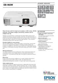 Epson EB-982W
User Manual
Epson EB-982W
User Manual
 Epson EB-G5100
Manual
Epson EB-G5100
Manual
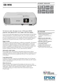 Epson EB-W06
User Manual
Epson EB-W06
User Manual
 Epson V11HA33920
User Manual
Epson V11HA33920
User Manual
 Epson V11HA73020
User Manual
Epson V11HA73020
User Manual
 Epson EMP-S3
User Manual
Epson EMP-S3
User Manual