Page 2 - Work area safety; Keep work area clean and well lit.; Electrical safety; Read all safety warnings and all instructions.; SAVE ALL WARNINGS AND INSTRUCTIONS FOR FUTURE REFERENCE; General Power Tool Safety Warnings
- 2- Work area safety Keep work area clean and well lit. Cluttered or dark areas invite accidents. Do not operate power tools in explosiveatmospheres, such as in the presence offlammable liquids, gases or dust. Power tools create sparks which may ignite the dustor fumes. Keep children and bystanders...
Page 3 - Cut-Off Machine Safety Warnings; Power tool use and care; Keep cutting tools sharp and clean.; Service
Cut-Off Machine Safety Warnings The guard provided with the tool must besecurely attached to the power tool andpositioned for maximum safety, so the leastamount of wheel is exposed towards theoperator. Position yourself and bystandersaway from the plane of the rotating wheel. The guard helps to prot...
Page 4 - Regularly clean the power tool’s air vents.; Kickback and related warnings
-4- wheel. Proper wheel flanges support the wheel thus reducing the possibility of wheelbreakage. Do not use worn down wheels from largerpower tools. Wheel intended for larger power tool is not suitable for the higher speed of asmaller tool and may burst. The outside diameter and the thickness ofyou...
Page 5 - Additional Safety Warnings
-5- direction opposite to the wheel’s movement atthe point of snagging. Use special care when working corners,s h a r p e d g e s e t c . A v o i d b o u n c i n g a n dsnagging the accessory. Corners, sharp edges or bouncing have a tendency to snagt h e r o t a t i n g a c c e s s o r y a n d c a u...
Page 6 - US400 – Paint & Rust Surface Prep Wheel
extremely careful of dust disposal, materialsin fine particle form may be explosive. Do not throw dust on an open fire. Fine dust particles may burn explosively. When performing sanding and surfacep r e p a r a t i o n o p e r a t i o n s w i t h t o o lc o n n e c t e d t o a d u s t c o l l e c t ...
Page 7 - Symbols; Symbol
-7- IMPORTANT: Some of the following symbols may be used on your tool. Please study them and learn their meaning. Proper interpretation of these symbols will allow you to operate thetool better and safer. Symbols Symbol Designation / Explanation V Volts (voltage) A Amperes (current) Hz Hertz (freque...
Page 9 - Functional Description and Specifications; Disconnect the plug from the power source before making any; Such preventive; INTENDED USE
U LT R A -S A W -9- Functional Description and Specifications Disconnect the plug from the power source before making any assembly, adjustments or changing accessories. Such preventive safety measures reduce the risk of starting the tool accidentally. US40 Dremel ® Ultra-Saw Model number US40 * Rate...
Page 10 - Assembly
Disconnect the plug fromthe power source before m a k i n g a n y a s s e m b l y , a d j u s t m e n t s o rchanging accessories. Such preventive safety measures reduce the risk of starting the toolaccidentally. The Lock Bolt which attaches the cutting wheelto the tool should be turned CLOCKWISE to...
Page 11 - DUST EXTRACTION; Dust Port Adapter; SIDE HANDLE
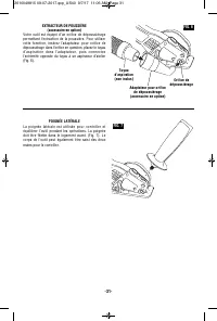
-11- DUST EXTRACTION (Optional accessory) Your tool is equipped with a dust port for dustextraction. To use this feature, insert dustport adapter into dust port, attach vacuumh o s e i n t o t h e a d a p t e r , t h e n c o n n e c t t h eopposite end of the hose to a shop vacuumcleaner (Fig. 6). D...
Page 12 - PADDLE SWITCH WITH; Paddle; Introduction; Thank you for purchasing the Dremel US40.; Operating Instructions
H o l d t h e t o o l w i t h b o t h hands while starting the tool, since torque from the motor can cause thetool to twist. Start the tool before applying to work and letthe tool come to full speed before contactingthe workpiece. Lift the tool from the workbefore releasing the switch. DO NOT turn t...
Page 13 - DEPTH ADJUSTMENT; Depth Adjustment; LINE GUIDE; Line Guide
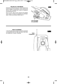
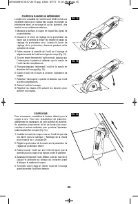
-13- DEPTH ADJUSTMENT Disconnect plug from power source. Loosenthe depth adjustment lever located on the rightside of the tool. The foot is spring loaded andwill lower automatically (Fig. 9).Tighten lever counter clockwise at the depthsetting desired. Check desired depth (Fig. 9). Depth Adjustment L...
Page 14 - Support
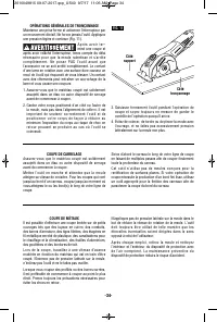
GENERAL CUT OFFS Maintain a firm grip and operate the switch witha decisive action. Never force the tool. Use alight and continuous pressure (Fig. 11). After completing a cut andt h e s w i t c h h a s b e e n released, be aware of the necessary time ittakes for the wheel to come to a complete stopd...
Page 16 - When using the straight edge guide on
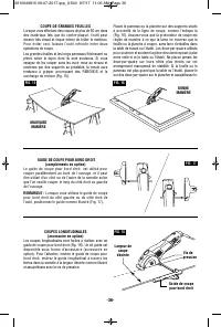
RIP CUTS (Optional attachment) Rip cuts are easy to do with a straight edgeguide (Fig. 18). Straight edge guide is availableas an accessory. To attach, insert straight edgeguide, insert fence through slots in foot todesired width as shown and secure with the setscrew. FIG. 18 Set Screw Desired Width...
Page 17 - RIP BOARD GUIDE; Rip Board; SURFACE PREPARATION; Allow the tool to reach full speed before
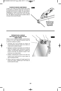
-17- RIP BOARD GUIDE When rip cutting large sheets, the straightedge guide may not allow the desired width ofcut. Clamp or nail a straight piece of 1" (25mm) lumber to the sheet as a guide (Fig. 19).Use the left side of the foot against the boardguide. Rip Board Guide FIG. 19 SURFACE PREPARATION...
Page 18 - Maintenance Information
Metal Surface Prep BladeUS400 Non-woven abrasive wheel for heavy rust removal and paint removal from metal. Concrete Surface Prep BladeUS410 Diamond Embedded wheel for thinset removal and paint removal from concrete andbrick. Wood Carbide WheelUS500 Abrasive cutting wheel with carbide grit which is ...
Page 20 - Trouble Shooting
-20- Trouble Shooting Read instruction manual first! Remove plug from the power source beforemaking adjustments or assembling the wheel. TROUBLE: TOOL WILL NOT START PROBLEM 1. Power cord is not plugged in. 2. Power source fuse or circuit breaker tripped.3. Cord damaged.4. Burned out switch. 5. Padd...
Page 21 - CANADA; Giles Tool Agency; OR; 7 Granger Av.; Dremel; UNITED STATES; OUTSIDE CONTINENTAL UNITED STATES; See your local distributor or write to
-21- Your Dremel product is warranted against defective material or workmanship for a period of two years fromdate of purchase. In the event of a failure of a product to conform to this written warranty, please take thefollowing action: 1. DO NOT return your product to the place of purchase. 2. Care...
Page 22 - Sécurité du lieu de travail; Maintenez le lieu de travail propre et bien éclairé.; Sécurité électrique; Symboles relatifs à la sécurité
-22- Sécurité du lieu de travail Maintenez le lieu de travail propre et bien éclairé. Les risques d’accident sont plus élevés quand ontravaille dans un endroit encombré ou sombre. N’utilisez pas d’outils électroportatifs dans desatmosphères explosives, comme par exemple enp r é s e n c e d e g a z ,...
Page 23 - Maintenez les outils coupants affûtés et propres.; Entretien
-23- Avertissements relatifs à la sécurité pour la machine à tronçonner Le dispositif de protection doit être fermement fixé àl’outil électroportatif et positionné pour un maximumde sécurité en s’arrangeant pour que la plus petiteportion possible de meule exposée soit tournée versl’utilisateur. Posi...
Page 24 - Avertissements sur les rebonds
-24- forces latérales à ces meules peuvent les faire éclater. U t i l i s e z t o u j o u r s d e s b r i d e s d e m e u l e n o nendommagées ayant un diamètre qui convient à lameule sélectionnée. Des brides de meule appropriées soutiennent la meule, réduisant ainsi la possibilité que lameule se ca...
Page 25 - Avertissements supplémentaires concernant la sécurité
façon à vous permettre de résister aux forces derebond. Utilisez toujours la poignée auxiliaire, quandelle vous a été fournie, pour un contrôle maximum durebond ou de la réaction de couple qui se produitpendant la mise en marche de l’outil. L’utilisateur peut contrôler les réactions de couple ou les...
Page 27 - Symboles; Symbole
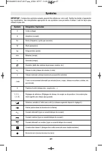
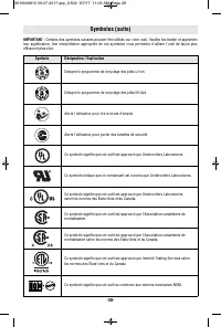
-27- IMPORTANT : Certains des symboles suivants peuvent être utilisés sur votre outil. Veuillez les étudier et apprendre leur signification. Une interprétation appropriée de ces symboles vous permettra d'utiliser l'outil de façon plusefficace et plus sûre. Symboles Symbole Désignation / Explication ...
Page 30 - Assemblage; d e u x
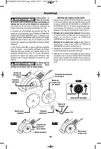
-30- Assemblage D é b r a n c h e z l a fiche de la prise de courant avant d'effectuer quelque assemblage ouréglage que ce soit ou de changer les accessoires. C e s m e s u r e s d e s é c u r i t é p r é v e n t i v e r é d u i s e n t l erisque d'une mise en marche accidentelle de l'outil. Le boul...
Page 32 - Consignes de fonctionnement
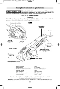
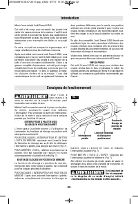
-32- Introduction Merci d’avoir acheté l’outil Dremel US40. Cet outil a été conçu pour accomplir des projets trèsvariés à la maison et autour de la maison. L’outil DremelUS40 permet d’accomplir les tâches plus rapidement etplus efficacement qu’avec les divers outils qui seraientnécessaires pour acco...
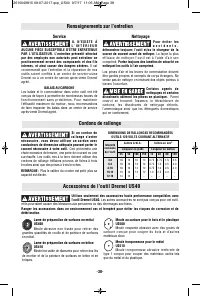
Page 38 - Accessoires de l’outil Dremel US40; Renseignements sur l’entretien; S i u n c o r d o n d e
Accessoires de l’outil Dremel US40 Utilisez seulement des accessoires haute performance compatibles avecl’outil Dremel US40. Les autres accessoires ne sont pas conçus pour cet outil, et ils pourraient causer des blessures aux personnes ou des dommages aux biens. Ranger les accessoires dans un enviro...
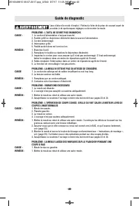
Page 40 - Guide de diagnostic
-40- Guide de diagnostic Lisez d’abord le mode d’emploi ! Retirez la fiche de la prise de courant avant deprocéder à de quelconques réglages ou de monter la meule. PROBLÈME : L’OUTIL NE SE MET PAS EN MARCHE. CAUSE : 1. Le cordon d’alimentation n’est pas branché. 2. Fusible grillé ou disjoncteur décl...
Page 41 - OU; Garantie limitée de Dremel; À L’EXTÉRIEUR DU TERRITOIRE CONTINENTAL DES ÉTATS-UNIS
-41- Votre produit Dremel est garanti contre les vices de matériau ou de façon pendant un délai de deux ans à compter dela date d’achat. Dans l’hypothèse où le produit ne se conformerait pas à cette garantie écrite, veuillez procéder de lafaçon suivante : 1. NE RAPPORTEZ PAS votre produit à l’endroi...
Page 42 - Seguridad del área de trabajo; Mantenga el área de trabajo limpia y bien iluminada.; Seguridad eléctrica; Manténgase alerta, fíjese en lo que está haciendo y; GUARDE TODAS LAS ADVERTENCIAS E INSTRUCCIONES; Símbolos de seguridad
-42- Seguridad del área de trabajo Mantenga el área de trabajo limpia y bien iluminada. Las áreas desordenadas u oscuras invitan a que seproduzcan accidentes. No utilice herramientas mecánicas en atmósferase x p l o s i v a s , c o m o p o r e j e m p l o e n p r e s e n c i a d el í q u i d o s , g...
Page 43 - Advertencias de seguridad para máquinas de corte abrasivo; Uso y cuidado de las herramientas
-43- Advertencias de seguridad para máquinas de corte abrasivo El protector suministrado con la herramienta se debeinstalar firmemente en la herramienta mecánica y sedebe posicionar de manera que brinde la máximaseguridad, para que la cantidad de rueda que estéexpuesta hacia el operador sea mínima. ...
Page 44 - Retroceso y advertencias relacionadas.
Utilice únicamente ruedas de corte con aglomerador e f o r z a d a s o d e d i a m a n t e p a r a s u h e r r a m i e n t aeléctrica. El hecho de que un accesorio se pueda instalar en su herramienta eléctrica no garantiza unfuncionamiento seguro. La velocidad nominal del accesorio debe ser alm e n ...
Page 45 - Advertencias de seguridad adicionales
en el punto de pellizcamiento. Las ruedas abrasivastambién se pueden romper en estas condiciones. El retroceso es el resultado de la utilización indebida dela herramienta mecánica y/o de procedimientos ocondiciones de operación incorrectos, y se puede evitartomando las precauciones apropiadas que se...
Page 47 - Símbolos; Símbolo
-47- Símbolos IMPORTANTE: Es posible que algunos de los símbolos siguientes se usen en su herramienta. Por favor, estúdielos y aprenda su significado. La interpretación adecuada de estos símbolos le permitirá utilizar laherramienta mejor y con más seguridad. Símbolo Désignation / Explication V Volt ...
Page 50 - Ensamblaje; N o i n t e n t e m o n t a r
-50- Ensamblaje D e s c o n e c t e e l enchufe de la fuente de energía antes de realizar cualquier ensamblaje oajuste, o cambiar accesorios. Estas medidas de seguridad preventivas reducen el riesgo de arrancar laherramienta accidentalmente. El perno de fijación que sujeta la rueda de corte a laherr...
Page 58 - Accesorios Dremel US40; Utilice únicamente accesorios de alto rendimiento Dremel US40.; Cordones de extensión; Servicio; S i e s n e c e s a r i o u n
Accesorios Dremel US40 Utilice únicamente accesorios de alto rendimiento Dremel US40. Otros accesorios no están diseñados para esta herramienta y pueden causar lesiones corporales o daños materiales. Almacene los accesorios en un entorno seco y templado para evitar la corrosión y el deterioro. -58- ...
Page 60 - Resolución de problemas
-60- Resolución de problemas Lea primero el manual de instrucciones! Retire el enchufe de la fuente de alimentación antes de hacer ajustes o ensamblar la rueda. DIFICULTAD: LA HERRAMIENTA NO ARRANCA PROBLEMA 1. El cable de alimentación no está enchufado. 2. El fusible de la fuente de alimentación se...
Page 64 - CANADÁ; Garantía limitada de Dremel; ESTADOS; FUERA DE LOS TERRITORIOS
Su producto Dremel está garantizado contra defectos de material o de fabricación durante un período de dos años apartir de la fecha de compra. En caso de que un producto no se ajuste a esta garantía escrita, por favor, tome lasmedidas siguientes: 1. NO devuelva el producto al lugar de compra. 2. Emp...