Page 3 - into any language or computer file, in any form or by any means—; TRADEMARK ACKNOWLEDGMENTS
DISCLAIMERS The information in this manual has been carefully checked and is believed to be accurate. Cypress Technology assumes no responsibility for any infringements of patents or other rights of third parties which may result from its use.Cypress Technology assumes no responsibility for any inac...
Page 4 - SAFETY PRECAUTIONS; Always follow basic safety precautions to reduce the risk of fire,; REVISION HISTORY; DATE
SAFETY PRECAUTIONS Please read all instructions before attempting to unpack, install or operate this equipment and before connecting the power supply.Please keep the following in mind as you unpack and install this equipment:• Always follow basic safety precautions to reduce the risk of fire, electr...
Page 5 - CONTENTS; Technical Specifications
CONTENTS 1. Introduction ......................................................12. Applications .....................................................13. Package Contents ..........................................14. System Requirements ......................................25. Features ................
Page 6 - switch between them. This unit comes with full support for 18Gbps
1 1. INTRODUCTION This 8 by 8 Matrix provides the ability to connect up to eight 4K UHD HDMI sources to up to eight 4K UHD HDMI displays and freely switch between them. This unit comes with full support for 18Gbps (600Mhz) resolutions up to, and including 4K@60Hz (4:4:4, 8-bit) as well as support fo...
Page 7 - • 1×Operation Manual; SYSTEM REQUIREMENTS; • HDMI source equipment such as media players, video game
2 • 1×Operation Manual 4. SYSTEM REQUIREMENTS • HDMI source equipment such as media players, video game consoles or set-top boxes. • HDMI receiving equipment such as HDTVs, monitors or audio amplifiers. • The use of “Premium High Speed HDMI” cables is highly recommended. 5. FEATURES • HDMI 2.0a and ...
Page 8 - OPERATION CONTROLS AND FUNCTIONS
3 6. OPERATION CONTROLS AND FUNCTIONS 6.1 Front Panel POWER 8x8 4K UHD+ Matrix IN 1 IN 2 IN 3 IN 4 OUT A OUT B OUT C OUT D CANCEL IN 5 OUT E IN 6 OUT F IN 7 OUT G IN 8 OUT H CONFIRM ENTER MENU PRESET ALL LOCK + - MUTE + 1 2 3 5 7 9 11 4 6 8 10 12 13 1 POWER: Press this button to power the unit on (g...
Page 9 - Note: If a USB device requiring more than 1A is connected, the
4 9 ALL: Press this button to select all outputs simultaneously for routing. Next, press the “IN” key of the input (1~8) you wish to route to all outputs. Finally, press “CONFIRM” to confirm your selection and execute the routing change. 10 PRESET: Press to enter the preset recall menu in the LCD wi...
Page 11 - LEVEL 1; EDID Setup; Drivers Setup; Keypad Action; Network Status
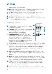
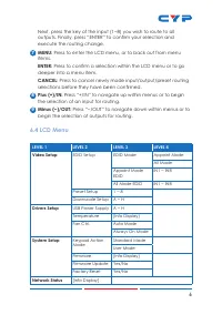
6 Next, press the key of the input (1~8) you wish to route to all outputs. Finally, press “ENTER” to confirm your selection and execute the routing change. 7 MENU: Press to enter the LCD menu, or to back out from menu items. ENTER: Press to confirm a selection within the LCD menu or to go deeper int...
Page 12 - Mode Static; IR Cable Pin Assignments; UNIT; TxD
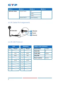
7 LEVEL 1 LEVEL 2 LEVEL 3 LEVEL 4 Network Setup Mode Static IP:Mask:Gate: Mode DHCP [Info Display] 6.5 IR Cable Pin Assignments 3 12 InfraredPowerGround IR Extender 6.6 RS-232 Protocol UNIT TERMINAL SERIAL PORT SETTINGS Pin Pinout Pin Pinout Baud Rate 19200 1 1 Data Bits 8 2 TxD 2 RxD Parity Bits No...
Page 13 - To access Telnet; the IP address of the unit and “23”, then hit “Enter”.
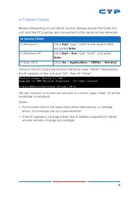
8 6.7 Telnet Control Before attempting to use Telnet control, please ensure that both the unit and the PC/Laptop are connected to the same active networks. To access Telnet In Windows 7 Click Start , type “cmd” in the search field, and press Enter . In Windows XP Click Start > Run , type “cmd”, a...
Page 14 - Reset Ethernet settings to the
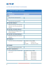
9 6.8 RS-232 and Telnet Commands 6.8.1 General & System Commands COMMAND DESCRIPTION VARIABLES HELP Show the full command list. ? Show the full command list. SET FACTORY DEFAULT Reset all settings to the factory defaults. Unit will automatically reboot. SET FACTORY IPCONFIG DEFAULT Reset...
Page 17 - Set all outputs to display input N1.
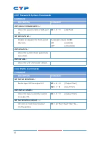
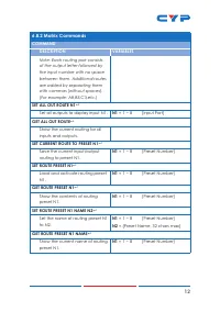
12 6.8.2 Matrix Commands COMMAND DESCRIPTION VARIABLES Note: Each routing pair consists of the output letter followed by the input number with no space between them. Additional routes are added by separating them with commas (without spaces). (For example: A8,B5,C3,etc.) SET ALL OUT ROUTE N1 Set a...
Page 18 - Enable or disable the A/V mute
13 6.8.2 Matrix Commands COMMAND DESCRIPTION VARIABLES SET OUT N1 MASK N2 Enable or disable the A/V mute of output N1. N1 = A ~ H [Output Port] Available values for N2 : ON [Mute A/V] OFF [Unmute A/V] GET OUT N1 MASK Show the current A/V mute state of output N1. N1 = A ~ H [Output Port] SET IN N...
Page 19 - SET OUT N1 4K2K DOWNSCALE MODE N2; GET OUT N1 4K2K DOWNSCALE MODE; Enable or disable the test pattern; GET PATTERN N1 MODE; Available values for
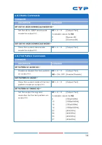
14 6.8.2 Matrix Commands COMMAND DESCRIPTION VARIABLES SET OUT N1 4K2K DOWNSCALE MODE N2 Set the 4K to 1080P downscale mode for output N1. N1 = A ~ H [Output Port] Available values for N2 : 0 [Bypass 4K] 2 [Downscale] GET OUT N1 4K2K DOWNSCALE MODE Show the current downscale mode for output N1. ...
Page 20 - GET PATTERN N1 TYPE
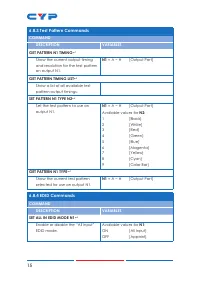
15 6.8.3 Test Pattern Commands COMMAND DESCRIPTION VARIABLES GET PATTERN N1 TIMING Show the current output timing and resolution for the test pattern on output N1. N1 = A ~ H [Output Port] GET PATTERN TIMING LIST Show a list of all available test pattern output timings. SET PATTERN N1 TYPE N2 ...
Page 21 - Show the current “All Input” EDID; SET ALL IN EDID N1; Set the EDID to use when the EDID; GET ALL IN EDID
16 6.8.4 EDID Commands COMMAND DESCRIPTION VARIABLES GET ALL IN EDID MODE Show the current “All Input” EDID mode state. SET ALL IN EDID N1 Set the EDID to use when the EDID mode is set to “All Input”. Available values for N1 : 1 [Internal 1] 2 [Internal 2] 3 [Internal 3] 4 [Internal 4] 5 [Intern...
Page 22 - Set EDID N2 as the EDID to use; GET IN N1 EDID; Show the EDID currently used with; GET ALL IN EDID LIST; Show the current EDID selections
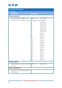
17 6.8.4 EDID Commands COMMAND DESCRIPTION VARIABLES SET IN N1 EDID N2 Set EDID N2 as the EDID to use with input N1 in “Appoint” mode. N1 = 1 ~ 8 [Input Port] Available values for N2 : 1 [Internal 1] 2 [Internal 2] 3 [Internal 3] 4 [Internal 4] 5 [Internal 5] 6 [Internal 6] 7 [User 1] 8 [User 2] 9...
Page 23 - Show the full list of available
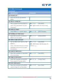
18 6.8.4 EDID Commands COMMAND DESCRIPTION VARIABLES GET IN EDID LIST Show the full list of available EDIDs. SET EDID N1 NAME N2 Set a custom name for EDID N1. Note: Only User EDIDs may be renamed. N1 = 7~14 [User EDID] N2 = {EDID Name, 32 chars max} GET EDID N1 NAME Show EDID N1’s current nam...
Page 24 - Set the HDCP mode for input N1.; GET IN N1 HDCP MODE
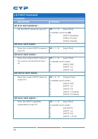
19 6.8.5 HDCP Commands COMMAND DESCRIPTION VARIABLES SET IN N1 HDCP MODE N2 Set the HDCP mode for input N1. N1 = 1 ~ 8 [Input Port] Available values for N2 : 0 [HDCP Disabled] 1 [Follow Source] 2 [Follow Display] GET IN N1 HDCP MODE Show the current HDCP mode of input N1. N1 = 1 ~ 8 [Input Port]...
Page 26 - Show the current gateway.; Note: Commands will not be executed unless followed by a carriage
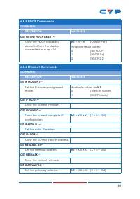
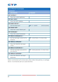
21 6.8.6 Ethernet Commands COMMAND DESCRIPTION VARIABLES GET GATEWAY Show the current gateway. GET MAC ADDR Show the MAC address. SET TELNET PORT N1 Set the Telnet port. N1 = 0 ~ 65535 [Port Number] GET TELNET PORT Show the current Telnet port. GET HOSTNAME Show the current hostname. SET W...
Page 27 - • Device Discovery APP; dealer and save it in a directory where you can easily find it.
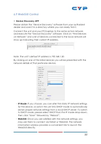
22 6.9 WebGUI Control • Device Discovery APP Please obtain the “Device Discovery” software from your authorized dealer and save it in a directory where you can easily find it. Connect the unit and your PC/Laptop to the same active network and execute the “Device Discovery” software. Click on “Find D...
Page 28 - • WebGUI Control Page; By default, both the Username and Password are “admin” for
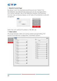
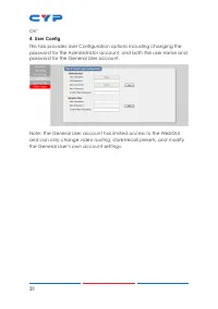
23 • WebGUI Control Page By default, both the Username and Password are “admin” for the WebGUI. The administrator password can be changed within the “System Settings” tab of the WebGUI if desired. The following function tabs will always display on left side of the WebGUI to aid with navigation. Note...
Page 29 - • Video Routing; To begin assigning a new video route, please click the button of the
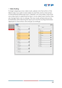
24 • Video Routing To begin assigning a new video route, please click the button of the HDMI output you wish to send video to and then click on the button of the preferred HDMI input port. If desired, you may select more than one output prior to selecting the input. As you select each button they wi...
Page 30 - • Output Edit; A variety of output settings, including name, muting, test pattern; Pattern Color Control:; pattern when “Pattern” is selected as the input source.
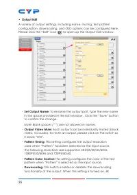
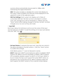
25 • Output Edit A variety of output settings, including name, muting, test pattern configuration, downscaling, and OSD options can be configured here. Please click the “Edit” icon ( ) to open up the Output Edit window. - Set Output Name: To rename the output port, type the new name in the space pro...
Page 31 - • Input Edit
26 sources will be automatically downscaled to 1080p while maintaining the original framerate. - OSD: This switch enables or disables the custom text display for this output. When enabled, the OSD text will be displayed in the upper-left corner of the selected output. - OSD Text Settings: Each outpu...
Page 32 - • Preset Setting; Once you have the matrix set the way you like, you can
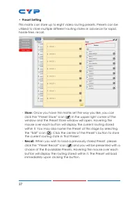
27 • Preset Setting This matrix can store up to eight video routing presets. Presets can be utilized to store multiple different routing states in advance for rapid, hassle-free, recall. - Store: Once you have the matrix set the way you like, you can click the “Preset Store” icon ( ) in the upper ri...
Page 33 - • Customer EDID Settings; To upload a user EDID, please click the “Upload” button next to
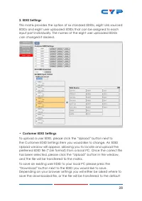
28 2. EDID Settings This matrix provides the option of six standard EDIDs, eight sink sourced EDIDs and eight user uploaded EDIDs that can be assigned to each input port individually. The names of the eight user uploaded EDIDs can changed if desired. • Customer EDID Settings To upload a user EDID, p...
Page 34 - download location on your PC. To change the name of a Customer; • Sink EDID Download; “Download” button. Depending on your browser settings you will; • Set EDID Input Content; to be assigned to each individual input, selecting “ALL” allows for a; • EDID Source; Note: In most cases, assigning a new EDID to an input will cause the; • Unit's Default EDIDs
29 download location on your PC. To change the name of a Customer EDID, type the new name in the space provided, then click on the “Save Name” button. • Sink EDID Download To save the EDID from one of the connected displays to your local PC, select the appropriate sink from the dropdown list then pr...
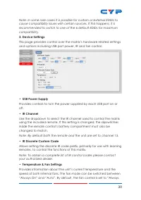
Page 35 - USB Power Supply; Provides controls to turn the power supplied by each USB port on or; IR Channel; inside the remote control’s battery compartment must also be; IR Discrete Custom Code; remotes, to control the functions of this matrix.; Temperature & Fan Settings; speed of both internal fans. The fan mode can be switched between
30 Note: In some rare cases it is possible for custom or external EDIDs to cause compatibility issues with certain sources. If this happens, it is recommended to switch to one of the 6 default EDIDs for maximum compatibility. 3. Device Settings This page provides control over the matrix’s hardware r...
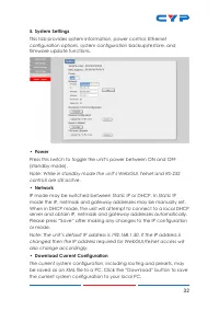
Page 37 - Power; Press this switch to toggle the unit’s power between ON and OFF; Network; IP mode may be switched between Static IP or DHCP. In Static IP; Download Current Configuration; be saved as an XML file to a PC. Click the “Download” button to save
32 5. System Settings This tab provides system information, power control, Ethernet configuration options, system configuration backup/restore, and firmware update functions. • Power Press this switch to toggle the unit’s power between ON and OFF (standby mode). Note: While in standby mode the unit’...
Page 38 - Restore Current Configuration; XML file. Click the “Choose File” button to locate the saved XML file,; Reset to Default; reset is complete, the unit will reboot automatically.; • Firmware Upgrade; To update the unit's firmware, click the “Choose File” button to open
33 • Restore Current Configuration Previously saved system configurations may be restored from a saved XML file. Click the “Choose File” button to locate the saved XML file, then click the “Restore” button.• Reset to Default Press this button to reset the unit to its factory default state. After the...
Page 39 - CONNECTION DIAGRAM
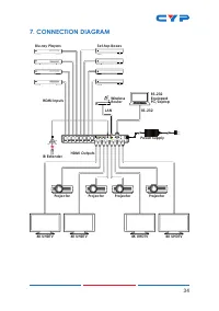
34 7. CONNECTION DIAGRAM 1 2 3 4 5 6 7 8 HDMI IN A B C D E F G H HDMI OUT USB 5V/1A OUT 1 2 3 4 5 6 7 8 CONTROL RS232 SERVICE DC 24V IR IN 7m 3m 3m 60° PRESET ALL INFO MUTE - / OUT + / IN ENTER CANCEL MENU CR-177 1 / A 2 / B 3 / C 4 / D 8 / H 5 / E 6 / F 7 / G Blu-ray Players Projector Projector Pro...
Page 40 - Metal
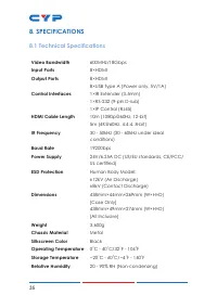
35 8. SPECIFICATIONS 8.1 Technical Specifications Video Bandwidth 600MHz/18Gbps Input Ports 8×HDMI Output Ports 8×HDMI 8×USB Type A (Power only, 5V/1A) Control Interfaces 1×IR Extender (3.5mm) 1×RS-232 (9-pin D-sub) 1×IP Control (RJ45) HDMI Cable Length 10m (1080p@60Hz, 12-bit) 5m (4K@60Hz, 4:4:4, 8...
Page 41 - Power Consumption; Video Specifications; Input
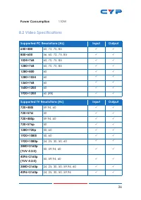
36 Power Consumption 110W 8.2 Video Specifications Supported PC Resolutions (Hz) Input Output 640×480 60, 72, 75, 85 800×600 56, 60, 72, 75, 85 1024×768 60, 70, 75, 85 1280×768 60, 70, 75, 85 1280×800 60 1280×1024 60 1360×768 60 1600×1200 60 1920×1200 60 (RB) Supp...
Page 42 - Consumer Electronics Control
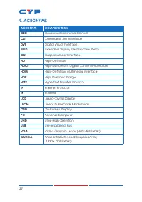
37 9. ACRONYMS ACRONYM COMPLETE TERM CEC Consumer Electronics Control CLI Command Line Interface DVI Digital Visual Interface EDID Extended Display Identification Data GUI Graphical User Interface HD High-Definition HDCP High-bandwidth Digital Content Protection HDMI High-Definition Multimedia Inter...