Page 7 - Getting Started
C H A P T E R 1 Introduction Thank you for choosing the Cisco RV340 router. This guide describes how to install and manage your router.This chapter includes information to help you get started on your device. Your Cisco RV340 comes withdefault settings. However, your internet service provider (ISP) ...
Page 9 - Launch Setup Wizard
To reboot the router, press the reset button with a paper clip or pen tip for lessthan 10 seconds. To reset the router to factory default settings, press and hold the reset buttonfor 10 seconds. RESET Launch Setup Wizard From the Launch Setup Wizard page, you can follow the instructions that guide y...
Page 10 - Troubleshooting Tips; User Interface
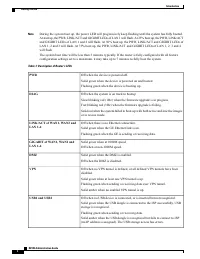
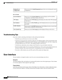
Directs you to the Config Management page where you can manage the router ’ s configuration. Backup DeviceConfiguration Device Status Directs you to the System Summary page that displays the IPv4 and IPv6 configuration, and firewall status on the device. System Summary Directs you to the VPN Status ...
Page 13 - System Summary
C H A P T E R 2 Status and Statistics This section provides information on the various configuration settings of your device and contains thefollowing topics: • System Summary, page 7 • TCP/IP Services, page 9 • Port Traffic, page 9 • WAN QoS Statistics, page 10 • Application Statistics, page 11 • C...
Page 16 - WAN QoS Statistics
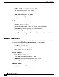
• Rx Bytes – Number of packets received, measured in bytes. • Tx Packets – Number of packets sent on the port. • Tx Bytes – Number of packets sent and measured in bytes. • Packet Error – Details about the error packets. • Refresh – To refresh the displayed statistics. • Reset Counters – To reset all...
Page 17 - Application Statistics
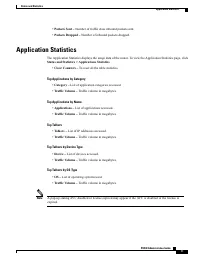
• Packets Sent – Number of traffic class inbound packets sent. • Packets Dropped – Number of inbound packets dropped. Application Statistics The Application Statistics displays the usage data of the router. To view the Application Statistics page, click Status and Statistics > Applications Statis...
Page 18 - DHCP Bindings
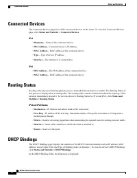
Connected Devices The Connected Devices page lists all the connected devices on the router. To view this Connected Devicespage, click Status and Statistics > Connected Devices . IPv4 • Hostname – Name of the connected device. • IPv4 Address – Connected device ’ s IP Address. • MAC Address – MAC a...
Page 19 - Mobile Network; VPN Status
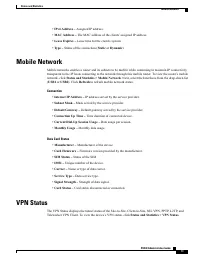
• IPv4 Address – Assigned IP address. • MAC Address – The MAC address of the clients ’ assigned IP address. • Lease Expires – Lease time for the client ’ s system. • Type – Status of the connection ( Static or Dynamic ). Mobile Network Mobile networks enables a router and its subnets to be mobile wh...
Page 21 - View Logs
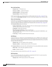
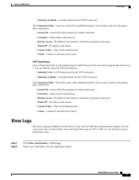
• Tunnel(s) Available – Available tunnels for the PPTP connection. The Connection Table – shows the status of the established tunnels. You can also connect or disconnect these connections. • Session ID – Session ID of the proposed or current connection. • Username – Name of the connected user. • Rem...
Page 24 - File Management
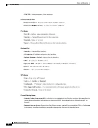
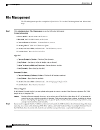
File Management The File Management provides a snapshot of your device. To view the File Management info, follow thesesteps: Step 1 Click Administration> File Management. to see the following information: System Information • Device Model – Model number of the device. • PID VID – PID and VID numb...
Page 25 - Manual Upgrade; Auto Update
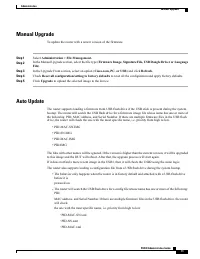
Manual Upgrade To update the router with a newer version of the firmware. Step 1 Select Administration > File Management. Step 2 In the Manual Upgrade section, select the file type ( Firmware Image, Signature File, USB Dongle Driver or Language File ). Step 3 In the Upgrade From section, select a...
Page 26 - Diagnostic; License
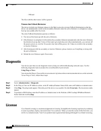
◦ PID.xml The files with the other names will be ignored. Firmware Auto Fallback Mechanism The device includes two firmware images in the flash to provide an Auto Fallback Mechanism so that thedevice can automatically switch to the secondary firmware when the active firmware is corrupted or cannotbo...
Page 27 - Request a Smart Account
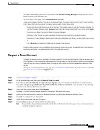
To register and manage your new Cisco product click Smart Licensing Manager and register for a Cisco Smart account if you don't have one. To access the License page, select Administration > License . A pop-up will appear stating if you are in Evaluation Mode. You must register your Cisco Product ...
Page 28 - Smart Software Licensing Status; Certificate
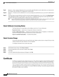
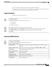
Step 9 Optional — Enter company information. If you selected the option No under account authorization, you must provide the company name and address by completing the required fields. Step 10 Optional — Nominate users for administrative access by entering the email ID of the users you select for ad...
Page 30 - Config Management
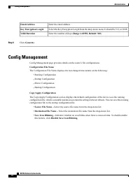
Enter the email address. Email Address Select the Key Encryption Length from the drop-down menu. It should be 512, or 2048. Key Encryption Length Enter the number of days ( Range 1-10950, Default: 360 ). Valid Duration Step 4 Click Generate . Config Management Config Management page provides details...
Page 32 - Initial Setup Wizard
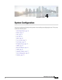
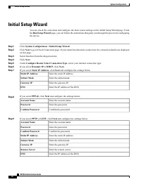
Initial Setup Wizard You can check the connection and configure the basic router settings on the Initial Setup Wizard page. Fromthe Run Setup Wizard page, you can follow the instructions that guide you through the process for configuring the device. Step 1 Click System Configuration > Initial Set...
Page 34 - Log
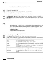
To configure the time and NTP server settings, follow these steps; Step 1 Click System Configuration > Time . Step 2 Set Time Zone – Select your time zone relative to Greenwich Mean Time (GMT). Step 3 Set Date and Time – Select Auto or Manual . a) Auto – Check Default or User Defined and enter a ...
Page 35 - Email Server
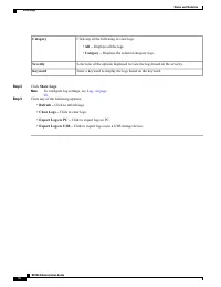
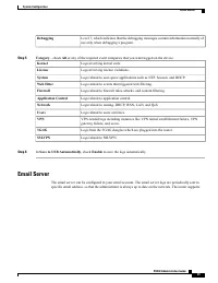
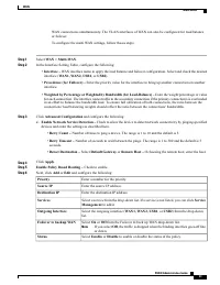
Level 7, which indicates that the debugging messages contain information normally ofuse only when debugging a program. Debugging Step 5 Category - check All or any of the required event categories that you want logged on the device. Logs involving kernel code. Kernel Logs involving license violation...
Page 36 - Remote Syslog Server; Email
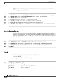
SMTP mail account configuration such as email addresses, password, message digest; optional parameters,SMTP server port number, SSL, TLS. Step 1 In the Email Server section, check Email Syslogs to enable the router to send email alerts when events are logged. Step 2 In the Email Settings section, cl...
Page 37 - User Accounts
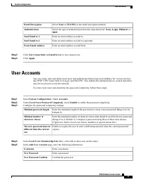
Select None or TLS/SSL as the email encryption method. Email Encryption Select the type of authentication from the drop-down list: None, Login, Plaintext or MD5 . Authentication Enter an email address to send to. Send Email to 1 Enter an email address to send to (optional). Send Email to 2 Enter an ...
Page 38 - Remote Authentication Service
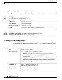
Displays password strength. Password Strength Meter Select a group (admin or guest) from the drop-down list. Group Step 6 Click Apply . Step 7 Click Edit or Delete to edit or delete an existing user. Step 8 In the Edit User Account page, enter the following information: Enter the old password. Old P...
Page 39 - User Groups
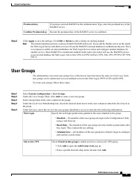
If you have selected RADIUS as the Authentication Type, enter the preshared key of theRADIUS server. Preshared-Key Reenter the preshared key of the RADIUS server to confirm it. Confirm Preshared-Key Step 2 Click Apply to save the settings. Click Edit or Delete to edit or delete an existing domain. T...
Page 40 - IP Address Group
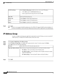
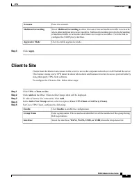
Check Permit in this group to enable access to a site-to-site VPN policy. • Click Add to open the Add Feature List pop up. • Select a profile from the drop down list and click Add. EzVPN/3rd Party Select a profile drop down list. SSL VPN Check Permit to enable PPTP authentication. PPTP VPN Check Per...
Page 42 - LLDP
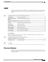
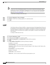
For discovery of Cisco Small Business products, Cisco provides a utility that works through a simpletoolbar on the web browser called FindIt. This utility discovers Cisco devices in the network and displaysbasic information, such as serial numbers and IP addresses. For more information and to downlo...
Page 43 - Automatic Updates
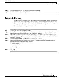
Step 6 To view details about an LLDP port, select the Local Port and click Detail . Step 7 To refresh the LLDP Neighbors Setting Table, click Refresh . Automatic Updates Upgrading to the latest firmware can help fix bugs and other intermittent issues on the router. For this purpose,the router can be...
Page 45 - WAN Settings
C H A P T E R 5 WAN This section covers the wide area network (WAN) and contains the following topics: • WAN Settings, page 39 • Multi-WAN, page 42 • Mobile Network, page 44 • Dynamic DNS, page 45 • Hardware DMZ, page 46 • IPv6 Transition, page 46 WAN Settings There are two physical WAN and VLAN int...
Page 50 - Mobile Network Setup
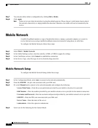
Step 7 You can also edit or delete a configuration by clicking Edit or Delete . Step 8 Click Apply . Some service providers do not allow to ping the default gateway. Please choose a valid remote host to detectthe network connectivity or simply disable the detection. Otherwise, the traffic will not b...
Page 51 - Bandwidth Cap Setting; Dynamic DNS
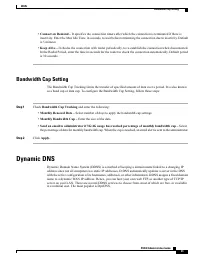
• Connect on Demand – It specifies the connection timers after which the connection is terminated if there is inactivity. Enter the Max Idle Time, in seconds, to wait before terminating the connection due to inactivity. Defaultis 5 minutes. • Keep Alive – It checks the connection with router periodi...
Page 55 - Traffic Classes
C H A P T E R 6 QoS This section describes the Quality of service (QoS), which is used to optimize network traffic in order toimprove the user experience. QoS controls and manages network resources by setting priorities for specifictypes of data (video, audio, files) on the network. It is exclusivel...
Page 56 - WAN Queuing
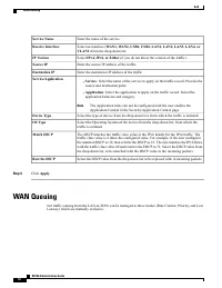
Enter the name of the service. Service Name Select an interface ( WAN1, WAN2, USB1, USB2, LAN1, LAN2, LAN3, LAN4, or VLAN1 ) from the drop-down list. Receive Interface Select IPv4, IPv6, or Either (if you do not know the version of the traffic). IP Version Enter the source IP address of the traffic....
Page 58 - Switch Classification
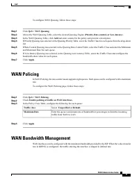
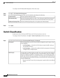
To configure the WAN Bandwidth Management, follow these steps: Step 1 Click QoS > WAN Bandwidth Management . Step 2 In the WAN Bandwidth Management Table, select the Interface and configure the following: Enter the upstream traffic rate in kb/s. Upstream (kb/s) Enter the downstream traffic rate i...
Page 59 - Switch Queuing
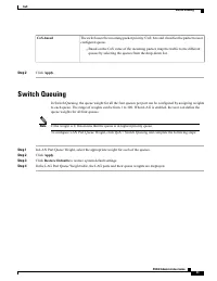
The switch uses the incoming packet priority 'CoS; bits and classifies the packet to userconfigured queue. • Based on the CoS value of the incoming packet, map the traffic to the differentqueues by selecting the queues from the drop-down list. CoS-based Step 2 Click Apply . Switch Queuing In Switch ...
Page 61 - Port Settings
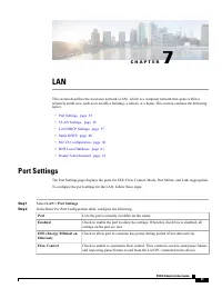
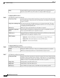
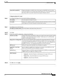
C H A P T E R 7 LAN This section describes the local area network (LAN), which is a computer network that spans within arelatively small area, such as in an office building, a school, or a home. This section contains the followingtopics: • Port Settings, page 55 • VLAN Settings, page 56 • LAN/DHCP S...
Page 62 - VLAN Settings
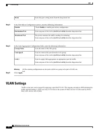
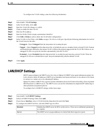
Select the port setting mode from the drop-down list. Mode Step 3 In the Port Mirror Configuration section, enter the following information: Check Enable to enable port mirror configuration. Enable Select anyone of the LANs (LAN1 to LAN4) from the drop-down list. Destination Port The port to monitor...
Page 66 - Static DHCP
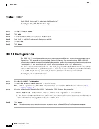
Static DHCP Static DHCP allows an IPv4 address to the defined MAC. To configure static DHCP follow these steps: Step 1 Select LAN > Static DHCP . Step 2 Click Add . Step 3 In the Static DHCP Table, enter a name in the Name field. Step 4 Enter the IPv4 and MAC addresses in the respective fields. S...
Page 69 - IGMP Proxy
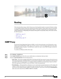
C H A P T E R 8 Routing This section describes routing, which is the process of selecting the best paths in a network. Dynamic routingis a networking technique that provides optimal data routing. Dynamic routing enables routers to select pathsaccording to real-time logical network layout changes. Th...
Page 70 - RIP
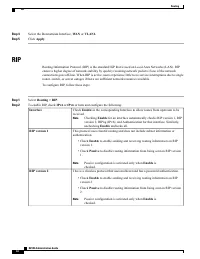
Step 4 Select the Downstream Interface, WAN or VLAN1. Step 5 Click Apply . RIP Routing Information Protocol (RIP) is the standard IGP that is used on Local Area Networks (LAN). RIPensure a higher degree of network stability by quickly rerouting network packets if one of the networkconnections goes o...
Page 71 - Static Routing
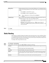
Routing Information Protocol next generation (RIPng) uses User Datagram Packets(UDP) to send routing information. This is based on RIP version 2 but used for IPv6routing. • Check Enable to enable RIP IPv6 routing. • Check Passive to disable sending RIPng version. Passive configuration is activated o...
Page 73 - Basic Settings
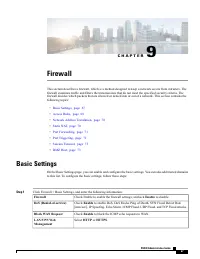
C H A P T E R 9 Firewall This section describes a firewall, which is a method designed to keep a network secure from intruders. Thefirewall examines traffic and filters the transmissions that do not meet the specified security criteria. Thefirewall decides which packets that are allowed or denied in...
Page 74 - Access Rules
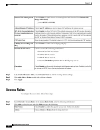
Check Enable to enable remote web management and enter the Port ( Default 443, Range 1025-65535 ). • Select HTTP or HTTPS . Remote Web Management Check Any IP Address or enter a range of IP addresses for remote access. Allowed Remote IP Address Check Enable to allow SIP ALG. This embeds messages of ...
Page 77 - Port Forwarding
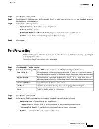
Step 3 Click Service Management . Step 4 To add a service, click Add under the Service table. To edit or delete a service, select the row and click Edit or Delete . The fields open for modification. Step 5 Configure the following services: • Application Name – Name of the service or application. • P...
Page 78 - Port Triggering
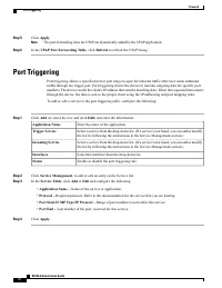
Step 5 Click Apply . The port forwarding rules for UPnP are dynamically added by the UPnP application. Note Step 6 In the UPnP Port Forwarding Table , click Refresh to refresh the UPnP listing. Port Triggering Port triggering allows a specified port or port range to open for inbound traffic after us...
Page 81 - VPN Setup Wizard
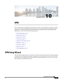
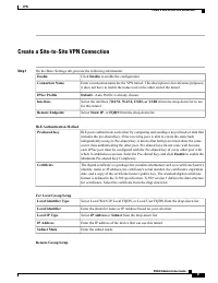
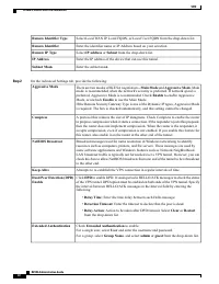
C H A P T E R 10 VPN This section describes a Virtual Private Network (VPN), which is used to establish an encrypted connectionover a less secure network. Virtual private networks ensure secure connections to an underlying networkinfrastructure. A tunnel establishes a private network that can send d...
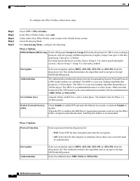
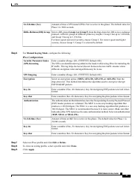
Page 83 - IPSec Profiles
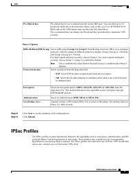
Pre-shared key to use to authenticate the remote IKE peer. You can enter up to 30keyboard characters or hexadecimal values, such as My_@123 or 4d795f40313233.Both ends of the VPN tunnel must use the same Pre-shared Key.We recommend that you change the Pre-shared Key periodically to maximize VPNsecur...
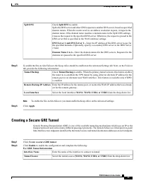
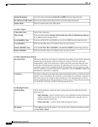
Page 89 - Creating a Secure GRE Tunnel
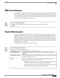
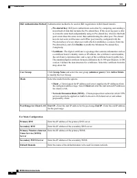
Check Split DNS to enable. Splits the DNS server and other DNS requests to another DNS server, based on specifieddomain names. When the router receives an address resolution request, it inspects thedomain name. If the domain name matches a domain name in the Split DNS settings,it passes the request ...
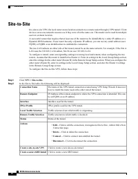
Page 91 - Client to Site
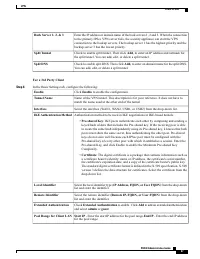
Enter the netmask. Netmask Select Multicast forwarding to allow the router forward multicast traffic to networks where other multicast devices are receptive. Multicast forwarding prevents the forwardingof multicast traffic to networks where there are receptive no nodes. Click the link toconfigure th...
Page 95 - Teleworker VPN Client
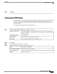
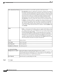
Step 8 Click Apply. Teleworker VPN Client The Teleworker VPN Client feature minimizes the configuration requirements at remote locations by allowingthe device to work as a Cisco VPN hardware client. When the Teleworker VPN Client starts the VPNconnection, the IPSec VPN server pushes the IPSec polici...
Page 97 - PPTP Server; L2TP Server
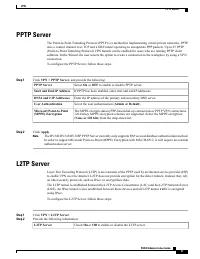
PPTP Server The Point-to-Point Tunneling Protocol (PPTP) is a method for implementing virtual private networks. PPTPuses a control channel over TCP and a GRE tunnel operating to encapsulate PPP packets. Up to 25 PPTP(Point-to-Point Tunneling Protocol) VPN tunnels can be enabled for users who are run...
Page 98 - Setup L2TP Over IPSec Server
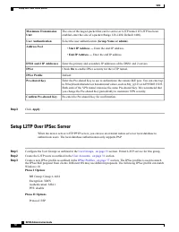
The size of the largest packet that can be sent over L2TP tunnel. If L2TP has beenenabled, enter the size of a packet (Range 128-1400, Default 1400). Maximum TransmissionUnit Select the user authentication ( Group Name or admin ). User Authentication • Start IP Address — Enter the start IP address. ...
Page 99 - SSL VPN
Encryption: 3DESAuthentication: SHA1 Step 4 Configure the L2TP server as outlined in the L2TP Server, on page 91 section. Enable the IPSec option and choose the new IPSec profile created in the previous step. Step 5 On Windows 10, create a new VPN connection. Go to Control Panel>Network, then Int...
Page 101 - VPN Passthrough
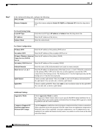
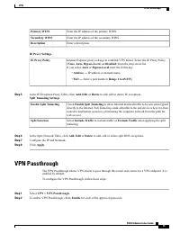
Enter the IP address of the primary WINS. Primary WINS Enter the IP address of the secondary WINS. Secondary WINS Enter a description. Description IE Proxy Settings Internet Explorer proxy settings to establish VPN tunnel. Select the IE Proxy Policy( None, Auto, Bypass-Local, or Disabled ) from the ...
Page 103 - Application Control Wizard
C H A P T E R 11 Security This section describes the network security, which consists of the policies adopted to prevent and monitorunauthorized access, misuse, modification, or denial of a computer network and contains the followingtopics: • Application Control Wizard, page 97 • Application Control...
Page 104 - Application Control
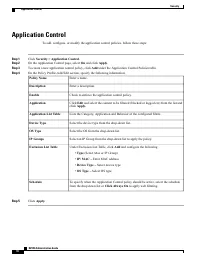
Application Control To add, configure, or modify the application control policies, follow these steps: Step 1 Click Security > Application Control . Step 2 On the Application Control page, select On and click Apply . Step 3 To create a new application control policy, click Add under the Applicati...
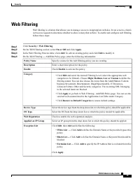
Page 105 - Web Filtering
Web Filtering Web filtering is a feature that allows you to manage access to inappropriate websites. It can screen a client ’ s web access requests to determine whether to allow or deny that website. To enable and configure web filtering,follow these steps: Step 1 Click Security > Web Filtering ....