Page 2 - DISCLAIMER; MODEL
DMA Series Installation Instructions 2 DISCLAIMER Legrand | AV and its affiliated corporations and subsidiaries (collectively “Legrand | AV”), intend to make this manual accurate and complete. However, Legrand | AV makes no claim that the information contained herein covers all details, conditions o...
Page 3 - DIMENSIONS
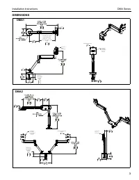
Installation Instructions DMA Series 3 DIMENSIONS DESKTOP THICKNESS RANGE 2.000 .375 50.8 9.5 1.9950.6 TILT RANGE 65 UP 10 DOWN DYNAMIC LIFT ARM LENGTH RANGE STRAIGHT = MAX FULL UP/DOWN = MIN 10.84 7.19 275.5 182.8 1.8446.7 90 MOUNTING PATTERN COMPATIBILITY 100 X 100 75 X 75 INTERFACE ROTATION RANGE...
Page 4 - LEGEND
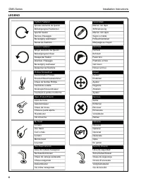
DMA Series Installation Instructions 4 LEGEND Tighten Fastener Apretar elemento de fijaciónBefestigungsteil festziehenApertar fixadorSerrare il fissaggioBevestiging vastdraaienSerrez les fixations Loosen Fastener Aflojar elemento de fijaciónBefestigungsteil lösenDesapertar fixadorAllentare il fissag...
Page 5 - TOOLS REQUIRED FOR INSTALLATION; Hardware bag
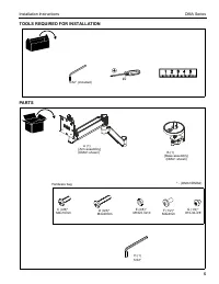
Installation Instructions DMA Series 5 TOOLS REQUIRED FOR INSTALLATION PARTS #2 5/32” (included) A (1) [Arm assembly] (DMA1 shown) C (4/8)* M4x10mm D (4/8)* M4x20mm E (4/8)* M10x5.3x10 5/32" H (1) F (1/2)* #10-32-3/8” * - (DMA1/DMA2) G (1/2)* M4x4mm Hardware bag B (1) [Base assembly] (DMA1 shown...
Page 6 - Assembly And Installation; Figure 1; Grommet Hole Option; Figure 4
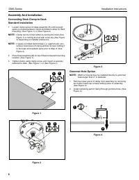
DMA Series Installation Instructions 6 Assembly And Installation Connecting Desk Clamp to DeskStandard Installation 1. Loosen clamp screw on base assembly (B) until enough space is created between clamp and base to allow for desk mounting. (See Figure 1) or (See Figure 2) NOTE: Clamp can be turned e...
Page 7 - Figure 5; Installing Arm to Base Assembly; If rotational stop is not desired, rotational; Display Installation - Standard Faceplate; Figure 8
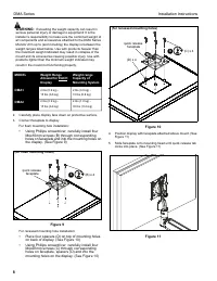
Installation Instructions DMA Series 7 3. Reattach removed piece of clamp and screws to assembly. (See Figure 5) 4. Tighten clamp using clamp screw until mount is securely fastened to desk. (See Figure 5) Figure 5 NOTE: Clamp can be turned either by turning the knob (See Figure 1) or turning the bol...
Page 8 - Figure 9
DMA Series Installation Instructions 8 WARNING: Exceeding the weight capacity can result in serious personal injury or damage to equipment! It is the installer’s responsibility to make sure the combined weight of all components and accessories attached to the DMA Series Monitor Arm up to (and includ...
Page 9 - Adjustments; Pitch Adjustment; Lift Arm Tension Adjustment
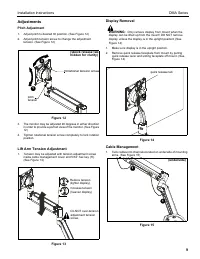
Installation Instructions DMA Series 9 Adjustments Pitch Adjustment 1. Adjust pitch to desired tilt position. (See Figure 12) 2. Adjust pitch tension screw to change the adjustment tension. (See Figure 12) Figure 12 3. The monitor may be adjusted 90 degrees in either direction in order to provide a ...
Page 10 - Pivot Adjustment Range; Tool Storage; of motion
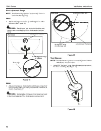
DMA Series Installation Instructions 10 Pivot Adjustment Range NOTE: This section only applies if the pivot stop screw is removed. (See Figure 6) DMA1 1. Adjust arm angle as desired up to 90 degrees in either direction. (See Figure 16) WARNING: Swinging the arm beyond 90 degrees may result in the mo...
Page 12 - DMA Series; AV
USA/International A 6436 City West Parkway, Eden Prairie, MN 55344 P 800.582.6480 / 952.225.6000 F 877.894.6918 / 952.894.6918 Europe A Franklinstraat 14, 6003 DK Weert, Netherlands P +31 (0) 495 580 852 F +31 (0) 495 580 845 Asia Pacific A Office No. 918 on 9/F, Shatin Galleria18-24 Shan Mei Street...