Casio CTK-401 - Manuals
Casio CTK-401 Synthesizer – Manual in PDF format online.
Manuals:
Manual Casio CTK-401


Summary
CONTENTS Specifications ................................................................................................................................... 1 Block Diagram ...................................................................................................................................
— 1 — SPECIFICATIONS GENERAL Keyboard: 49 standard-size keys, 4 octaves Tones: 100 Polyphony: 12 notes maximum (6 for certain tones) Auto accompaniment Rhythm patterns: 100 Tempo: Variable (236 steps, = 20 to 255) Chords: 2 fingering methods (CASIO CHORD, FINGERED) Rhythm controller: START/STOP, SYN...
— 2 — BLOCK DIAGRAM CPU MSM 6755B-17 LSI1 Keyboard Buttons LCD LCD Driver SED1278F0A LSI3 Reset IC IC1 Oscillator X1, Q1 Power Supply Circuit Q101 ~ Q103, D104 Power Amp. TA8248K IC101 Filter (L) Q104 Filter (R) Q105 Output VC VCC DVDD APO MD0 ~ MD7 MA0 ~ MA17 DC + 9 V IN DB4 ~ DB7 COM1 ~ COM16 SEG1...
Casio Synthesizers Manuals
-
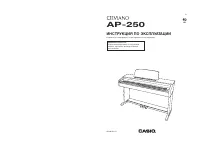 Casio AP-250
Manual
Casio AP-250
Manual
-
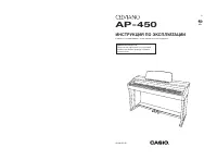 Casio AP-450
Manual
Casio AP-450
Manual
-
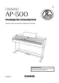 Casio AP-500
Manual
Casio AP-500
Manual
-
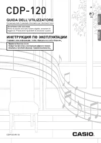 Casio CDP-120
Manual
Casio CDP-120
Manual
-
 Casio CTK-2000
Manual
Casio CTK-2000
Manual
-
 Casio CTK-2080
Manual
Casio CTK-2080
Manual
-
 Casio CTK-2200
Manual
Casio CTK-2200
Manual
-
 Casio CTK-230
Manual
Casio CTK-230
Manual
-
 Casio CTK-2300
Manual
Casio CTK-2300
Manual
-
 Casio CTK-240
Manual
Casio CTK-240
Manual
-
 Casio CTK-3000
Manual
Casio CTK-3000
Manual
-
 Casio CTK-3200
Manual
Casio CTK-3200
Manual
-
 Casio CTK-4200
Manual
Casio CTK-4200
Manual
-
 Casio CTK-4400
Manual
Casio CTK-4400
Manual
-
 Casio CTK-571
Manual
Casio CTK-571
Manual
-
 Casio CTK-591
Manual
Casio CTK-591
Manual
-
 Casio CTK-593
Manual
Casio CTK-593
Manual
-
 Casio CTK-6200
Manual
Casio CTK-6200
Manual
-
 Casio CTK-691
Manual
Casio CTK-691
Manual
-
 Casio CTK-7000
Manual
Casio CTK-7000
Manual