Page 2 - TABLE OF CONTENTS
INST ALLA TION MANUAL TABLE OF CONTENTS 2 Safety . . . . . . . . . . . . . . . . . . . . . . . . . . . . . . . . . 3-4 Operation . . . . . . . . . . . . . . . . . . . . . . . . . . . . . . 5-6 Cleaning and Maintenance . . . . . . . . . . . . . . . . . . 7 MotorGrease Filter(s)Non-Ducted Recirculatio...
Page 3 - SAFETY; READ AND SAVE THESE INSTRUCTIONS; INSTALLER: LEAVE THIS MANUAL WITH HOMEOWNER.; WARNING
INSTALLATION MANUAL SAFETY 3 READ AND SAVE THESE INSTRUCTIONS ! Intended for domestic cooking only ! INSTALLER: LEAVE THIS MANUAL WITH HOMEOWNER. In U.S.A., register your range hood online at www.broan-nutone.com In Canada, register your range hood online at www.broan.ca ! WARNING TO REDUCE THE RISK...
Page 4 - TO REDUCE THE RISK OF A RANGE TOP GREASE FIRE:; CAUTION
INST ALLA TION MANUAL SAFETY 4 ! WARNING TO REDUCE THE RISK OF A RANGE TOP GREASE FIRE: a) Never leave surface units unattended at high settings. Boilovers cause smoking and greasy spillovers that may ignite. Heat oils slowly on low or medium settings. b) Always turn hood ON when cooking at high hea...
Page 5 - Operation; BKDEG1 SERIES; FILTER CLEANING REMINDER; LIGHT BUTTON
INSTALLATION MANUAL OPERA TION 5 Operation Always turn your hood on before you begin cooking to establish an air flow in the kitchen. Let the blower run for a few minutes to clear the air after you turn off the range. This will help keep the whole kitchen cleaner and fresher. Operate the hood as fol...
Page 6 - OPERA; BLOWER SWITCH
INST ALLA TION MANUAL OPERA TION 6 BLOWER SWITCH I Turns blower on to LOW speed. • Turns blower OFF. II Turns blower on to HIGH speed. LIGHT SWITCH I Turns light on in LOW intensity. • Turns light OFF. II Turns light on to HIGH intensity. BKSA1 SERIES LIGHT SWITCH Turns light OFF. I Turns light on...
Page 7 - CLEANING AND MAINTENANCE; Cleaning and Maintenance; MOTOR; Avoid when choosing a detergent:; bleach; PAINTED FINISH CLEANING:
INSTALLATION MANUAL CLEANING AND MAINTENANCE 7 Cleaning and Maintenance Proper maintenance of the Range Hood will assure proper performance of the unit. MOTOR The motor is permanently lubricated and never needs oiling. If the motor bearings make excessive or unusual noise, replace the motor with the...
Page 8 - INST; Install Ductwork (Ducted Installations Only)
INST ALLA TION MANUAL INST ALLA TION 8 Recommended Tools and Accessoriesfor Installation • Measuring tape • Phillips screwdriver no. 2 • Flat blade screwdriver (to open knockout holes) • Drill, 1/8” drill bit and 1½” hole saw (to mark holes for ducting and cut electrical access hole) • 7/64” drill b...
Page 9 - TION; Contents; Maximum Duct Lengths Recommended
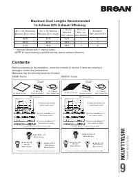
INSTALLATION MANUAL INSTALLA TION 9 Contents Before proceeding to the installation, check the contents of the box. If items are missing or damaged, contact the manufacturer. Make sure that the following items are included: BKDB1 Series BKDEG1 Series (1) 3¼” X 10” D AMPER ASSEMBLY * (1) 7” R OUND D U...
Page 11 - Prepare the Hood; illustrations may sligthly differ from your unit.
INSTALLATION MANUAL INSTALLA TION 11 Prepare the Hood 1 ] If present, remove all protective polyfilm from the hood and/or parts. 2 ] Using the finger cup or tab, remove the grease filters from the hood by pushing down and tilting filter out . 3 ] Remove the EZ1 brackets from inside the hood by c...
Page 12 - NON-DUCTED INSTALLATION ONLY
INST ALLA TION MANUAL INST ALLA TION 12 5 ] Remove 7” Round Duct Plate from top/back of hood (see illustration below). Keep the screws for further use. RECIRCULATION COVER PLATE SCREWS 6 ] Remove Electrical Power Cable Knockout from top (vertical exhaust) or back (horizontal exhaust) of hood. Instal...
Page 13 - DUCTED INSTALLATION ONLY; TIP
INSTALLATION MANUAL INSTALLA TION 13 DUCTED INSTALLATION ONLY TIP : Inser t a small length of duct over the 3¼” x 10” damper assembly (for rectangular ducting) or 7” round (for round ducting) and seal the joint using aluminum foil duct tape to ease connection with the house duct work. 8 ] Remove 3¼”...
Page 14 - Prepare the Hood Location; EZ1 one-person installation system; If replacing a hood and plan to use
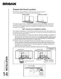
INST ALLA TION MANUAL INST ALLA TION 14 Prepare the Hood Location NOTE: Before star ting installation, read all the steps of these instructions.Use the illustration below to identify your kitchen cabinet type. EZ1 one-person installation system EZ1 installation is designed for use with kitchen cabin...
Page 17 - While holding the hood
INSTALLATION MANUAL INSTALLA TION 17 A B D C Install the Hood (EZ1 Bracket) 1 ] Run house power cable between service panel and hood location. 2 ] There are 2 pairs of recessed holes on each side of the top of the hood (on rear: A and B , on front C and D on illustration below); these holes allow th...
Page 18 - ] For framed cabinet
INST ALLA TION MANUAL INST ALLA TION 18 7 ] For framed cabinet , secure the hood to the EZ1 brackets using 4 no. 8-18 x 1/2” metal screws (included in parts bag). Insert 2 screws per side, in the slots (as shown in insets on illustration below). 8 ] For frameless cabinet , secure the hood to the cab...
Page 19 - Standard Installation (without EZ1 brackets)
INSTALLATION MANUAL INSTALLA TION 19 Standard Installation (without EZ1 brackets) 1 ] Use the proper diagram below for placement of duct work and electrical cutout in cabinet or wall. For a non-ducted installation, DO NOT cut a duct access hole, only cut the hole for electrical wiring. 2 ] Install p...
Page 21 - Connect the Wiring
INSTALLATION MANUAL INSTALLA TION 21 Connect the Wiring 1 ] Connect House Power Cable to range hood wiring: BLACK to BLACK, WHITE to WHITE and GREEN or bare wire under GREEN ground screw. ! WARNING Risk of electric shock. Electrical wiring must be done by qualifi ed personnel in accordance with all ...
Page 22 - Ducted Installation Only:
INST ALLA TION MANUAL INST ALLA TION 22 Light Bulbs (BKSA1 and BKSH1 Series only) 1 ] Align the bulb leads with the small indentations located on the border of the lamp location on hood (see inset above), then install the bulbs by placing the bulb leads into their grooves in the socket. 2 ] Gently p...
Page 23 - WIRING DIAGRAMS; BKDB1 SERIES
INSTALLATION MANUAL WIRING DIAGRAMS 23 12 3 4 5 6 1 2 3 4 J6 Ov err ide J4 LED J1 0 Interf ace 1 2 3 4 5 6 7 8 User int erf ace mount ed to J1 0 on bac k of contr ol boar d. J1 T ransf ormer J2 P o we r , Mot or 5 4 3 2 1 5 4 3 2 1 6 7 C ontr ol Boar d R R BL BL BK W BK BK W G/Y R (Lo w) O (Medium) ...
Page 25 - BKSH1 SERIES
INSTALLATION MANUAL WIRING DIAGRAMS 25 G/Y W BK O R F AN MO T O R BN BN/W G/Y R (Lo w) BK (High) W 120 V A C Line Neutr al Gr ound BK BK Mot or S witch Light S witch Y (Lo w) BL (High) W W BK BK COLOR CODE BK BL BN BLACK BLUE BROWN R W Y RED WHITE YELLOW BN/W G/Y O BROWN/WHITE GREEN/YELLOW ORANGE W ...
Page 26 - SERVICE P
INST ALLA TION MANUAL SERVICE P AR TS 26 K EY NO . P ART NO . D ESCRIPTION Q UANTITY 30" B LACK 30" S TAINLESS 30" W HITE 36" B LACK 36" S TAINLESS 36" W HITE 1 S97020029 R ECIRCULATION COVER PLATE , B LACK ( INCLUDING SCREWS ) 1 1 S97020030 R ECIRCULATION COVER PLATE , W HIT...
Page 29 - BKSA1 SERIES
INSTALLATION MANUAL SERVICE P AR TS 29 K EY NO . P ART NO . D ESCRIPTION Q UANTITY 30" S TAINLESS 30" W HITE 30" B LACK 1 S97020029 R ECIRCULATION COVER PLATE , B LACK ( INCLUDING SCREWS ) 1 S97020030 R ECIRCULATION COVER PLATE , W HITE ( INCLUDING SCREWS ) 1 S97020031 R ECIRCULATION COV...
Page 30 - ARRANTY
INST ALLA TION MANUAL W ARRANTY 30 Limited Warranty Warranty Period and Exclusions: Broan-NuTone LLC and Venmar Ventilation ULC (either being the “Company”) warrants to the original consumer purchaser of its product (“you”) that the product (the “Product”) will be free from material defects in the P...
Page 31 - MANUEL D’INST; TABLE DES MA
MANUEL D’INST ALLATION TABLE DES MA TIÈRES 31 31 Sécurité . . . . . . . . . . . . . . . . . . . . . . . . . . . . . 32-33 Fonctionnement . . . . . . . . . . . . . . . . . . . . . . . 34-35 Nettoyage et entretien . . . . . . . . . . . . . . . . . . . . . 36 MoteurFiltre(s) à graissesFiltre(s) de reci...
Page 32 - SÉCURITÉ; AVERTISSEMENT; VEUILLEZ LIRE ET CONSERVER CES DIRECTIVES; INSTALLATEUR : LAISSER CE MANUEL AU PROPRIÉTAIRE.
MANUEL D’INST ALLA TION SÉCURITÉ 32 ! AVERTISSEMENT AFIN DE RÉDUIRE LES RISQUES D’INCENDIE, D’ÉLECTROCUTION OUDE BLESSURES CORPORELLES, SUIVEZ LES DIRECTIVES SUIVANTES : • N’utilisez cet appareil que de la façon prévue par le manufacturier. Si vous avez des questions, contactez le manufacturier à l’...
Page 33 - AFIN DE RÉDUIRE LES RISQUES DE FEU DE CUISINIÈRE :; ATTENTION
MANUEL D’INST ALLATION SÉCURITÉ 33 ! AVERTISSEMENT AFIN DE RÉDUIRE LES RISQUES DE FEU DE CUISINIÈRE : a) Ne jamais laisser les appareils de cuisson sans surveillance lorsqu’ils sont réglés à feu vif. Les débordements engendrent de la fumée et des déversements graisseux pouvant s’enflammer. Chauffez ...
Page 34 - FONCTIONNEMENT; Fonctionnement; SÉRIES BKDB1; RAPPEL D’ENTRETIEN DES FILTRES
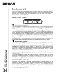
MANUEL D’INST ALLA TION FONCTIONNEMENT 34 Fonctionnement Toujours mettre en marche la hotte avant de commencer la cuisson afin d’établir une circulation d’air dans la cuisine. Laisser également la hotte fonctionner quelques minutes après l’arrêt de la cuisinière afin de nettoyer l’air. Cela aidera à...
Page 35 - COMMUTATEUR DE L’ÉCLAIRAGE
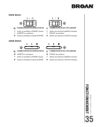
MANUEL D’INST ALLATION FONCTIONNEMENT 35 COMMUTATEUR DE L’ÉCLAIRAGE I Allume les lumières à BASSE intensité. • ÉTEINT les lumières. II Allume les lumières à HAUTE intensité. SÉRIE BKSA1 COMMUTATEUR DU VENTILATEUR I Active le ventilateur à BASSE vitesse. • ARRÊTE le ventilateur. II Active le ventilat...
Page 36 - NETTO; Nettoyage et entretien; MOTEUR; À éviter lors du choix du détergent :; NETTOYAGE DES SURFACES PEINTES :
MANUEL D’INST ALLA TION NETTO YAGE ET ENTRETIEN 36 Nettoyage et entretien L’entretien adéquat de la hotte préservera ses performances. MOTEUR Le moteur est lubrifié en permanence et n’a pas besoin d’être huilé. Si les roulements du moteur sont anormalement bruyants, remplacer le moteur uniquement pa...
Page 37 - Outils et accessoires recommandés pour l’installation; Pour connaître les lignes directrices de l’ADA(
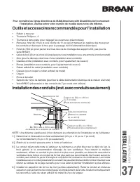
MANUEL D’INST ALLATION INSTALLA TION 37 Outils et accessoires recommandés pour l’installation • Ruban à mesurer • Tournevis Phillips n° 2 • Tournevis à lame plate (pour dégager les ouvertures préamorcées) • Perceuse, foret de 1/8 po et scie cloche de 1½ po (pour marquer les repères des trous pour le...
Page 38 - Contenu; Longueurs maximales de conduit recommandées
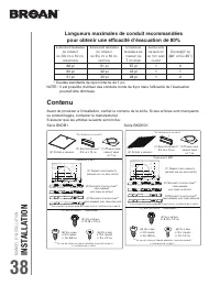
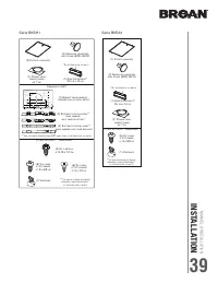
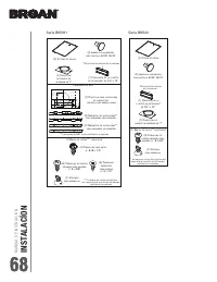
MANUEL D’INST ALLA TION INST ALLA TION 38 Contenu Avant de procéder à l’installation, vérifier le contenu de la boîte. Si des ar ticles sont manquants ou endommagés, contacter le manufacturier. S’assurer que les ar ticles suivants sont inclus : Série BKDB1 Série BKDEG1 *** L E SAC DE PIÈCES SE TROUV...
Page 40 - Préparation de la hotte
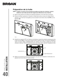
MANUEL D’INST ALLA TION INST ALLA TION 40 Préparation de la hotte 1 ] Retirer toute présence de pellicule de plastique protectrice sur la hotte et/ou ses pièces. 2 ] Enlever les filtres à graisses en insérant un doigt dans la prise concave de chaque filtre à graisses ou en tirant sur la languette, p...
Page 41 - INSTALLATION EN RECIRCULATION SEULEMENT
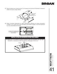
MANUEL D’INST ALLATION INSTALLA TION 41 5 ] Retirer la plaque pour conduit rond de 7 po du dessus de la hotte (voir l’illustration ci-dessous). Garder les vis pour usage ultérieur. PLAQUE VIS 6 ] Retirer l’ouverture préamorcée du câble d’alimentation électrique du dessus (évacuation verticale) ou de...
Page 42 - INSTALLATION AVEC CONDUITS SEULEMENT; TRUC
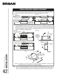
MANUEL D’INST ALLA TION INST ALLA TION 42 INSTALLATION AVEC CONDUITS SEULEMENT TRUC : Glisser une petite longueur de conduit par dessus l’adaptateur/volet de 3¼ po x 10 po (pour un conduit rectangulaire) ou de 7 po rond (pour un conduit rond) et sceller le joint à l’aide de ruban adhésif d’aluminium...
Page 43 - Préparation de l’emplacement de la hotte; Système d’installation par une personne EZ1; Lors d’un remplacement d’une hotte, si vous prévoyez utiliser
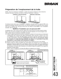
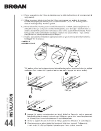
MANUEL D’INST ALLATION INSTALLA TION 43 Préparation de l’emplacement de la hotte NOTE : Avant de commencer l’installation, veuillez lire toutes les étapes de cette instruction.Identifier votre type d’armoire de cuisine à l’aide de l’illustration ci-dessous. Système d’installation par une personne EZ...
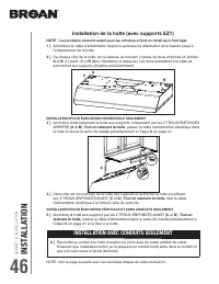
Page 46 - Installation de la hotte (avec supports EZ1); Tout en retenant la hotte
MANUEL D’INST ALLA TION INST ALLA TION 46 A B D C Installation de la hotte (avec supports EZ1) 1 ] Acheminer le câble d’alimentation depuis le panneau de distribution de la maison jusqu’à l’emplacement de la hotte. 2 ] De chaque côté de la hotte, sur le dessus, se trouvent 2 paires de trous enfoncés...
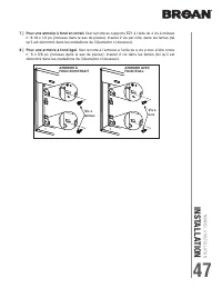
Page 47 - ] Pour une armoire à fond en retrait; ] Pour une armoire à fond égal
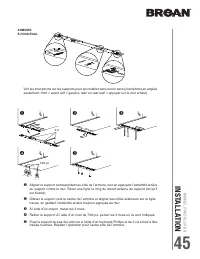
MANUEL D’INST ALLATION INSTALLA TION 47 7 ] Pour une armoire à fond en retrait , fixer la hotte au supports EZ1 à l’aide de 4 vis à métaux n° 8-18 x 1/2 po (incluses dans le sac de pièces). Insérer 2 vis par côté, dans les fentes (tel qu’il est démontré dans les médaillons de l’illustration ci-desso...
Page 48 - Installation standard (sans supports EZ1)
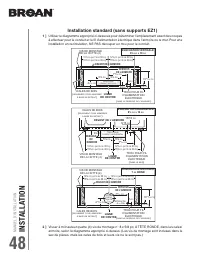
MANUEL D’INST ALLA TION INST ALLA TION 48 Installation standard (sans supports EZ1) 1 ] Utiliser le diagramme approprié ci-dessous pour déterminer l’emplacement exact des coupes à effectuer pour le conduit et le fil d’alimentation électrique dans l’armoire ou le mur. Pour une installation en recircu...
Page 49 - Installation de la hotte (installation standard)
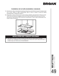
MANUEL D’INST ALLATION INSTALLA TION 49 Installation de la hotte (installation standard) 1 ] Acheminer le câble d’alimentation électrique du panneau de distribution jusqu’à l’emplacement de la hotte. Insérer le câble d’alimentation dans la hotte à travers le serre-fils installé précédemment à l’étap...
Page 50 - Branchement électrique
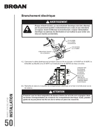
MANUEL D’INST ALLA TION INST ALLA TION 50 Branchement électrique ! AVERTISSEMENT Risque d’électrocution. Le raccordement électrique doit être effectué par du personnel qualifi é conformément aux codes et aux standards en vigueur. Avant d’effectuer le branchement, coupez l’alimentation électrique au ...
Page 51 - Ampoules; et; Installation du ou des filtres; Installation avec conduits seulement :; Installation en recirculation seulement :
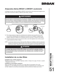
MANUEL D’INST ALLATION INSTALLA TION 51 Ampoules (Séries BKSA1 et BKSH1 seulement) 1 ] Pour chaque ampoule, aligner les conducteurs de l’ampoule avec les petits trous situés sur le bord de l’emplacement de l’ampoule sur la hotte (voir le médaillon ci-dessus), puis installer l’ampoule en glissant ses...
Page 52 - SCHÉMAS ÉLECTRIQUES; SÉRIE BKDB1
MANUEL D’INST ALLA TION SCHÉMAS ÉLECTRIQUES 52 12 3 4 5 6 1 2 3 4 J6 C ommande pr ior it air e J4 DEL J1 0 Interf ace 1 2 3 4 5 6 7 8 Int erf ace de l’utilisat eur connect ée à J1 0 à l’arr ièr e de la car te électr onique J1 T ransf ormat eur J2 Alimentation, Mot eur 5 4 3 2 1 5 4 3 2 1 6 7 C a rt ...
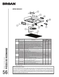
Page 53 - SÉRIE BKDEG1
MANUEL D’INST ALLATION SCHÉMAS ÉLECTRIQUES 53 12 3 4 5 6 1 2 3 4 J6 C ommande pr ior it air e J4 J1 0 Interf ace 1 2 3 4 5 6 7 8 Int erf ace de l’utilisat eur connect ée à J1 0 à l’arr ièr e de la car te électr onique J1 T ransf ormat eur J2 Alimentation, Mot eur 5 4 3 2 1 5 4 3 2 1 6 7 C a rt e éle...
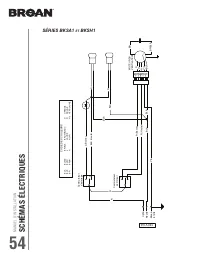
Page 54 - SÉRIES BKSA1
MANUEL D’INST ALLA TION SCHÉMAS ÉLECTRIQUES 54 V/J BLA N O R MO TEUR DU VENTILA TEUR BR BR/BLA V/J R (Basse) N (Haut e) BLA 120 V CA Ligne Neutr e Mise à la t err e N N C omm ut at eur d’éclair age J (Basse) BLE (Haut e) BLA BLA N N CODE DES COULEURS BLA BLE BR BLANC BLEU BRUN O R V/J ORANGE ROUGE V...
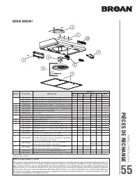
Page 55 - PIÈCES DE RECHANGE
MANUEL D’INST ALLATION PIÈCES DE RECHANGE 55 * A RTICLE NON ILLUSTRÉ . R EPÈRE Nº DE PIÈCE D ESCRIPTION Q UANTITÉ 30 PO N OIRE 30 PO I NOX . 30 PO B LANCHE 36 PO N OIRE 36 PO I NOX . 36 PO B LANCHE 1 S97020029 P LAQUE DE GRILLE DE RECIRCULATION , N OIRE ( AVEC VIS ) 1 1 S97020030 P LAQUE DE GRILLE D...
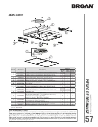
Page 57 - SÉRIE BKSH1
MANUEL D’INST ALLATION PIÈCES DE RECHANGE 57 R EPÈRE Nº DE PIÈCE D ESCRIPTION Q UANTITÉ 30 PO I NOX . 30 PO B LANCHE 30 PO N OIRE 1 S97020030 P LAQUE DE GRILLE DE RECIRCULATION , B LANCHE ( INCLUANT LES VIS ) 1 S97020031 P LAQUE DE GRILLE DE RECIRCULATION , I NOX . ( INCLUANT LES VIS ) 1 S97020029 P...
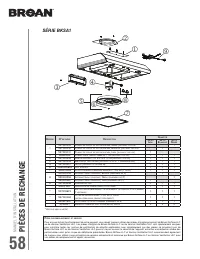
Page 58 - SÉRIE BKSA1
MANUEL D’INST ALLA TION PIÈCES DE RECHANGE 58 R EPÈRE Nº DE PIÈCE D ESCRIPTION Q UANTITÉ 30 PO I NOX . 30 PO B LANCHE 30 PO N OIRE 1 S97020029 P LAQUE DE GRILLE DE RECIRCULATION , N OIRE ( INCLUANT LES VIS ) 1 S97020030 P LAQUE DE GRILLE DE RECIRCULATION , B LANCHE ( INCLUANT LES VIS ) 1 S97020031 P...
Page 59 - GARANTIE
MANUEL D’INST ALLATION GARANTIE 59 Garantie limitée Période de garantie et exclusions : Broan NuTone LLC (la « Société ») ou Venmar Ventilation ULC et/ou son subsidiaire garantit au consommateur acheteur initial (« vous ») de son produit (le « Produit ») que celui-ci est exempt de tout vice de matér...
Page 60 - ÍNDICE
MANUAL DE INST ALACIÓN ÍNDICE 60 Seguridad . . . . . . . . . . . . . . . . . . . . . . . . . . . . 61-62 Funcionamiento . . . . . . . . . . . . . . . . . . . . . . . 63-64 Limpieza y mantenimiento . . . . . . . . . . . . . . . . . 65 MotorFiltro(s) de grasaFiltro(s) de recirculaciónHéliceLimpieza de...
Page 61 - SEGURID; ADVERTENCIA; LEA ESTAS INSTRUCCIONNES Y GUÁRDELAS; INSTALADOR: ENTREGUE ESTE MANUAL AL PROPIETARIO.
MANUAL DE INST ALACIÓN SEGURID AD 61 61 ! ADVERTENCIA PARA REDUCIR EL RIESGO DE INCENDIO, DESCARGA ELÉCTRICA O LESIÓN CORPORAL, RESPETE LAS SIGUIENTES INDICACIONE: • Utilice esta unidad únicamente de la forma en que indica el fabricante. Si tiene cualquier pregunta, póngase en contacto con el fabric...
Page 63 - FUNCIONAMIENTO; Funcionamiento; SERIES BKDB1; RECORDATORIO DE LIMPIEZA DE LOS FILTROS
MANUAL DE INST ALACIÓN FUNCIONAMIENTO 63 63 Funcionamiento Ponga la campana en marcha siempre antes de empezar a cocinar para crear una corriente de aire en la cocina.Deje funcionar el ventilador impelente varios minutos para limpiar el aire cuando ya haya apagado la cocina. De este modo, la cocina ...
Page 64 - INTERRUPTOR DE LA LUZ
MANUAL DE INST ALACIÓN FUNCIONAMIENTO 64 64 BKSA1 SERIES INTERRUPTOR DE LA LUZ APAGA la luz. I Enciende la luz a BAJA intensidad. II Enciende la luz a ALTA intensidad. BKSH1 SERIES INTERRUPTOR DEL VENTILADOR APAGA el ventilador. I Pone en marcha el ventilador a BAJA velocidad. II Pone en marcha ...
Page 65 - LIMPIEZA Y MANTENIMIENTO; Limpieza y mantenimiento
MANUAL DE INST ALACIÓN LIMPIEZA Y MANTENIMIENTO 65 65 Limpieza y mantenimiento El mantenimiento adecuado de la campana permitirá que funcione correctamente. MOTOR El motor está lubricado permanentemente y no necesita engrase nunca. Si los rodamientos del motor hacen un ruido excesivo o no habitual, ...
Page 66 - modelo en nuestro sitio web.
MANUAL DE INST ALACIÓN INST ALACÍON 66 66 66 Herramientas y accesorios recomendadospara la instalación • Cinta métrica • Destornillador Phillips n.° 2 • Destornillador de punta plana (para abrir los orificios punzonados) • Taladro, broca de 1/8” y serrucho de calar de 1½” (para cortar el orificio de...
Page 67 - Largos maximales recommandados de conducto; Contenido
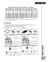
MANUAL DE INST ALACIÓN INSTALACÍON 67 67 67 * Codos estandardes con radio internal de 1 pulgada. Largos maximales recommandados de conducto para conseguir un rendimiento de 80% de evacuación de aire L ARGO MÁXIMO DE CONDUCTO DE 3¼” X 10”, HORIZONTAL L ARGO MÁXIMO DE CONDUCTO DE 3¼” X 10”, VERTICAL L...
Page 69 - Prepare la campana
MANUAL DE INST ALACIÓN INSTALACÍON 69 69 69 Prepare la campana 1 ] De haberla, retire de la campana y de todas las piezas la película protectora. 2 ] Use el orificio de agarre o la pestaña para retirar de la campana el o los filtros de grasa empujando hacia abajo e inclinando los filtros hacia fue...
Page 70 - INSTALACIÓN SIN CONDUCTOS ÚNICAMENTE
MANUAL DE INST ALACIÓN INST ALACÍON 70 70 70 5 ] Retire la placa para conducto redondo de 7” de la parte superior trasera de la campana y conserve los tornillos para usarlos posteriormente (véase la ilustración de abajo). PLACA DE CUBIERTA DE RECIRCULACIÓN TORNILLOS 6 ] Retire la parte punzonada par...
Page 71 - INSTALACIÓN CON CONDUCTOS ÚNICAMENTE; CONSEJO
MANUAL DE INST ALACIÓN INSTALACÍON 71 71 71 INSTALACIÓN CON CONDUCTOS ÚNICAMENTE CONSEJO : Introduzca una pequeña longitud de conducto en el conjunto de la clapeta de 3¼” x 10” (para un conducto rectangular) o en la placa para conducto redondo de 7” (para un conducto redondo) y selle la junta con ci...
Page 72 - Prepare la ubicación de la campana; Sistema de instalación EZ1 por una persona; Si
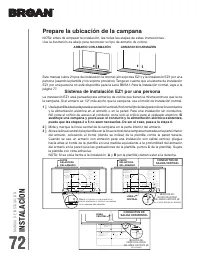
MANUAL DE INST ALACIÓN INST ALACÍON 72 72 72 Prepare la ubicación de la campana NOTA: antes de empezar la instalación, lea todas las etapas de estas instrucciones.Use la ilustración de abajo para reconocer su tipo de armario de cocina. Este manual cubre 2 tipos de instalación: la normal (sin soporte...
Page 75 - Mientras sujeta la campana
MANUAL DE INST ALACIÓN INSTALACÍON 75 75 75 A B D C INSTALACIÓN CON SALIDA HORIZONTAL INSTALACIÓN CON SALIDA VERTICAL Y INSTALACIÓN SIN CONDUCTOS OTA: N El procedimiento siguiente se aplica a las instalaciones en armarios con armazón y sin armazón. Instale la campana (Soporte EZ1) 1 ] Lleve el cable...
Page 76 - ] En los armarios con armazón; ] En los armarios sin armazón
MANUAL DE INST ALACIÓN INST ALACÍON 76 76 76 ARMARIO CON ARMAZÓN ARMARIO SIN ARMAZÓN 7 ] En los armarios con armazón , sujete la campana a los sopor tes EZ1 por medio de los (4) tornillos para metal no 8-18 x 1/2” (vienen en la bolsa de piezas). Introduzca (2) tornillos en cada lado, en las ranuras ...
Page 79 - Conecte el cableado
MANUAL DE INST ALACIÓN INSTALACÍON 79 79 79 Conecte el cableado 1 ] Conecte el cable de alimentación de la vivienda al cableado de la campana: El hilo NEGRO con el NEGRO, el BLANCO con el BLANCO y el VERDE o el hilo pelado con el tornillo VERDE de tierra. ! ADVERTENCIA Riesgo de descarga eléctrica. ...
Page 80 - Instale el o los filtros; Instalación con conductos únicamente:; Instalación sin conductos únicamente:
MANUAL DE INST ALACIÓN INST ALACÍON 80 80 80 Bombillas (Series BKSA1 y BKSH1 solamente) 1 ] Alinee los plomos de las bombillas con los pequeñas marcas situadas en el borde de la ubicación de la lámpara en la campana (véase el detalle arriba) e instale las bombillas colocando los plomos en sus acanal...
Page 81 - DIAGRAMAS DE C; SERIE BKDB1
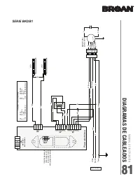
MANUAL DE INST ALACIÓN INSTALACÍON 81 MANUAL DE INST ALACIÓN DIAGRAMAS DE C ABLEADOS 81 81 81 12 3 4 5 6 1 2 3 4 J6 Int err upt or de an ulación J4 J1 0 Interf az 1 2 3 4 5 6 7 8 Int erf az de usuar io conect ado en J1 0 en la par te tr aser a de la placa electr ónica J1 T ransf ormador J2 P o tenci...
Page 82 - MANUAL DE INST; SERIE BKDEG1
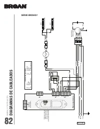
MANUAL DE INST ALACIÓN INST ALACÍON 82 MANUAL DE INST ALACIÓN DIAGRAMAS DE C ABLEADOS 82 82 82 12 3 4 5 6 1 2 3 4 J6 Int err upt or de an ulación J4 J1 0 Interf az 1 2 3 4 5 6 7 8 Int erf az de usuar io conect ado en J1 0 en la par te tr aser a de la placa electr ónica J1 T ransf ormador J2 P o tenc...
Page 83 - SERIES BKSA1
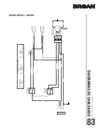
MANUAL DE INST ALACIÓN INSTALACÍON 83 MANUAL DE INST ALACIÓN DIAGRAMAS DE C ABLEADOS 83 83 83 V/AM B NE NA R MO T OR DEL VENTILADOR C C/B V/AM R (Baja) NE (Alt a) B 120 V CA Línea Neutr o T ierr a NE NE Int err upt or de lampar a AM (Baja) AZ (Alt a) B B NE NE C ÓDIGO DE COL ORES AM AZ B AMARILLO AZ...
Page 84 - PIEZAS DE REPUESTO
MANUAL DE INST ALACIÓN INST ALACÍON 84 MANUAL DE INST ALACIÓN PIEZAS DE REPUESTO 84 84 84 R EPUESTOS Y REPARACIONES Para que el aparato esté en buenas condiciones, use sólo repuestos genuinos Broan-NuTone LLC o Venmar Ventilation ULC. Los repuestos genuinos Broan-NuTone LLC o Venmar Ventilation ULC ...
Page 86 - SERIE BKSH1
MANUAL DE INST ALACIÓN INST ALACÍON 86 MANUAL DE INST ALACIÓN PIEZAS DE REPUESTO 86 86 86 SERIE BKSH1 * Í TEM NO MOSTRADO . R EPUESTOS Y REPARACIONES Para que el aparato esté en buenas condiciones, use sólo repuestos genuinos Broan-NuTone LLC o Venmar Ventilation ULC. Los repuestos...
Page 87 - SERIE BKSA1
MANUAL DE INST ALACIÓN INSTALACÍON 87 MANUAL DE INST ALACIÓN PIEZAS DE REPUESTO 87 87 87 SERIE BKSA1 R EPUESTOS Y REPARACIONES Para que el aparato esté en buenas condiciones, use sólo repuestos genuinos Broan-NuTone LLC o Venmar Ventilation ULC. Los repuestos genuinos Broan-NuTone ...
Page 88 - GARANTÍA
MANUAL DE INST ALACIÓN INST ALACÍON 88 MANUAL DE INST ALACIÓN GARANTÍA 88 88 88 Garantía limitada Periodo y exclusiones de la garantía: Broan-NuTone LLC o Venmar Ventilation ULC (sea esta la “Comp añía ”) garantiza al consumidor comprador original de su producto (“usted”) que el producto (el “Produc...


 Broan 403001
User Manual
Broan 403001
User Manual
 Broan 403004
User Manual
Broan 403004
User Manual
 Broan 403023
User Manual
Broan 403023
User Manual
 Broan 412401
User Manual
Broan 412401
User Manual
 Broan 412404
User Manual
Broan 412404
User Manual
 Broan 413004
User Manual
Broan 413004
User Manual
 Broan 413023
User Manual
Broan 413023
User Manual
 Broan 413604
User Manual
Broan 413604
User Manual
 Broan 423001
User Manual
Broan 423001
User Manual
 Broan 423004
User Manual
Broan 423004
User Manual
 Broan 423023
User Manual
Broan 423023
User Manual