Blanco BCG95X - Manuals
User Manual Blanco BCG95X


Summary
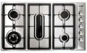
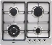
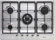
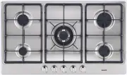
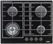
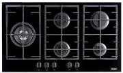
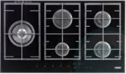
2 Natural U-LPG 1 Ultra rapid gas burner/Wok 15.0 MJ 15.0* MJ 3 Semi-rapid gas burner 7.3 MJ 6.9 MJ 4 Auxiliary gas burners 4.0 MJ 3.8 MJ 5 Fish gas burner 12.0 MJ 11.5 MJ 6 Right trivet 2 burners 7 Left trivet 2 burners 9 Central fish trivet 10 Burner 1 control knob 12 Burner 3 control knob (left b...
1) BURNERS A diagram is screen-printed above each knob onthe front panel. This diagram indicates to whichburner the knob in question corresponds. Afterhaving opened the gas mains or gas bottle tap, lightthe burners as described below: - Manual ignition P u s h a n d t u r n t h e k n o b c o r r e s...
5 CLEANING IMPORTANT: Always disconnect the appliance from the gasand electricity mains before carrying out anycleaning operation. 2) HOT PLATE Periodically wash the hot plate, the enamelled steelor cast iron pan support, the enamelled burner caps“A”, “B” and “C” and the burner heads “T” (see fig. 6...
Blanco Hobs Manuals
-
 Blanco BCCT60N
User Manual
Blanco BCCT60N
User Manual
-
 Blanco BCCT64X
User Manual
Blanco BCCT64X
User Manual
-
 Blanco BIC603S
User Manual
Blanco BIC603S
User Manual
-
 Blanco BIC604T
User Manual
Blanco BIC604T
User Manual
-
 Blanco BIC63T
User Manual
Blanco BIC63T
User Manual
-
 Blanco BIC64F
User Manual
Blanco BIC64F
User Manual
-
 Blanco BIC75T
User Manual
Blanco BIC75T
User Manual
-
 Blanco CG604WXFFC
User Manual
Blanco CG604WXFFC
User Manual
-
 Blanco CG705WXFFC
User Manual
Blanco CG705WXFFC
User Manual
-
 Blanco CG905WXFFC
User Manual
Blanco CG905WXFFC
User Manual
-
 Blanco CGG604WFFC
User Manual
Blanco CGG604WFFC
User Manual
-
 Blanco CGG905WFFC
User Manual
Blanco CGG905WFFC
User Manual
-
 Blanco CGG905WTFFC
User Manual
Blanco CGG905WTFFC
User Manual