Bertazzoni MAS96L1EXT - Manuals
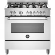
User Manual Bertazzoni MAS96L1EXT


Summary
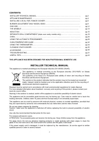
2 CONTENTS: INSTALLER TECHNICAL MANUAL…………………………………………………………………….. pg.2 APPLIANCE MAINTENANCE ....................................................................................................... pg.4 INSTALLING A DUAL FUEL RANGE COOKER ................................................................
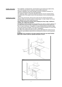
3 Installer information The installation, all adjustments, transformations and maintenance listed in this part of the manual must be carried out only by skilled personnel. Improper installation may cause damage to persons, animals or property, for which the manufacture will not be held responsible. ...
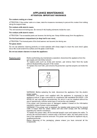
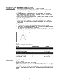
4 APPLIANCE MAINTENANCE ATTENTION: IMPORTANT WARNINGS For cookers resting on a base ATTENTION: If the cooker rests on a base, take the measures necessary to prevent the cooker from sliding along the support base. For cookers with electric ovens The unit becomes hot during use. Do not touch the heati...
Bertazzoni Ranges Manuals
-
 Bertazzoni HER100 6 MFE D CR T
User Manual
Bertazzoni HER100 6 MFE D CR T
User Manual
-
 Bertazzoni HER100 6 MFE D NET
User Manual
Bertazzoni HER100 6 MFE D NET
User Manual
-
 Bertazzoni HER100 6 MFE D VI T
User Manual
Bertazzoni HER100 6 MFE D VI T
User Manual
-
 Bertazzoni HER100 6 MFE T CR T
User Manual
Bertazzoni HER100 6 MFE T CR T
User Manual
-
 Bertazzoni HER100 6 MFE T NET
User Manual
Bertazzoni HER100 6 MFE T NET
User Manual
-
 Bertazzoni HER100 6 MFE T VI T
User Manual
Bertazzoni HER100 6 MFE T VI T
User Manual
-
 Bertazzoni HER106L2EAVT
User Manual
Bertazzoni HER106L2EAVT
User Manual
-
 Bertazzoni HER106L2ENET
User Manual
Bertazzoni HER106L2ENET
User Manual
-
 Bertazzoni HER120 6G MFE D CRT
User Manual
Bertazzoni HER120 6G MFE D CRT
User Manual
-
 Bertazzoni HER120 6G MFE D NET
User Manual
Bertazzoni HER120 6G MFE D NET
User Manual
-
 Bertazzoni HER120 6G MFE D VIT
User Manual
Bertazzoni HER120 6G MFE D VIT
User Manual
-
 Bertazzoni HER126G2EAVT
User Manual
Bertazzoni HER126G2EAVT
User Manual
-
 Bertazzoni HER126G2ENET
User Manual
Bertazzoni HER126G2ENET
User Manual
-
 Bertazzoni HER90 6 HYB S NET
User Manual
Bertazzoni HER90 6 HYB S NET
User Manual
-
 Bertazzoni HER90 6 MFE D CR T
User Manual
Bertazzoni HER90 6 MFE D CR T
User Manual
-
 Bertazzoni HER90 6 MFE D NET
User Manual
Bertazzoni HER90 6 MFE D NET
User Manual
-
 Bertazzoni HER90 6 MFE D VI T
User Manual
Bertazzoni HER90 6 MFE D VI T
User Manual
-
 Bertazzoni HER90 6 MFE S CR T
User Manual
Bertazzoni HER90 6 MFE S CR T
User Manual
-
 Bertazzoni HER90 6 MFE S NET
User Manual
Bertazzoni HER90 6 MFE S NET
User Manual
-
 Bertazzoni HER90 6 MFE S VI T
User Manual
Bertazzoni HER90 6 MFE S VI T
User Manual