Page 3 - FROM THE DESK OF OUR PRESIDENT
FROM THE DESK OF OUR PRESIDENT Dear new owner of a Bertazzoni appliance, I want to thank you for choosing one of our beautiful products for your home. My family started manufacturing kitchen appliances in Italy in 1882, building areputation for quality of engineering and passion for good food. Today...
Page 5 - USER MANUAL VALIDITY
USER MANUAL VALIDITY The following manual is valid for all the product codes mentioned below: • MAS365GASNEV • MAS365GASBIV • MAS365GASXVLP • MAS365GASXV • PRO365GASXV 5
Page 6 - CONTENTS
6 CONTENTS INSTALLATION MANUAL . . . . . . . . . . . . . . . . . . . . . . . . . . . . . . . . . . . . . . . . . . . . . . . . . . . . . . . . . . . . . . . . . . . . . . . . . . . 9 WARNINGS . . . . . . . . . . . . . . . . . . . . . . . . . . . . . . . . . . . . . . . . . . . . . . . . . . . . . . ...
Page 9 - WARNINGS; DO NOT install this range outdoors.
WARNINGS To ensure proper and safe operation, the appliance mustbe properly installed and grounded by a qualified technician.DO NOT attempt to adjust, repair, service, or replace anypart of your appliance unless it is specifically recommendedin this manual. All other servicing should be referred to ...
Page 10 - WARNING
WARNINGS Fig. 1 WARNING Warning-tipping hazard A child or adult can tip over the range andbe killed. Install the anti-tip device to the structureand/or the range. Verify the anti-tip devicehas been properly installed and engaged. Engage the range to the anti-tip device by anti-tip bracketsor anti-ti...
Page 11 - Cancer and Reproductive Harm —; DATA RATING LABEL
WARNINGS DO NOT lift the appliance by the range’s control panel. The unit is heavy and should be handled accordingly.Proper safety equipment such as gloves and adequatemanpower of at least two people must be used in movingthe range to avoid injury and to avoid damage to the unit orthe floor. Rings, ...
Page 12 - BEFORE INSTALLATION; resulting; TYPE OF GAS
BEFORE INSTALLATION • This appliance shall only be installed by an authorizedprofessional. • This appliance shall be installed in accordance with themanufacturer’s installation instructions. • This appliance must be installed in accordance with thenorms & standards of the country where it will b...
Page 13 - VENTILATION PREPARATION; SELECT HOOD AND BLOWER MODELS
VENTILATION PREPARATION This range will best perform when installed with Bertazzoniexhaust hoods. These hoods have been designed to workin conjunction with the Bertazzoni range and have thesame finish for a perfect look. Before installation of the exhaust hood, consult local orregional building and ...
Page 14 - SPECIFICATIONS
SPECIFICATIONS Fig. 2 • A 36″ • B 37″½ MAX A 27'' /8 1'' 15/16 25'' /16 2'' 1'' 5/8 32'' 3'' 3/4 - 5'' 1/2 5'' 1'' 5/8 1'' 1/8 '' / 23'' 7/8 3'' 7/16 3 '' 11/16 2'' 7/16 A B 14
Page 16 - CLEARANCES DIMENSIONS; CAUTION; CABINET
CLEARANCES DIMENSIONS INSTALLATION ADJACENT TO KITCHENCABINETS This range may be installed directly adjacent to existingcountertop high cabinets (36″ or 91.5 cm from the floor). For the best look, the worktop should be level with thecabinet countertop. This can be accomplished by raisingthe unit usi...
Page 17 - INSTALLATION REQUIREMENTS; ELECTRICAL; GAS
INSTALLATION REQUIREMENTS Fig. 5 Fig. 6 installation area for the connection ELECTRICAL A properly-grounded horizontally-mounted electrical receptacle should be installed no higher than 3″ (7.6 cm)above the floor, no less than 2″ (5 cm) and no more than 8″(20.3 cm) from the left side (facing product...
Page 18 - ELECTRICAL CONNECTION; Verify proper operation after servicing.
ELECTRICAL CONNECTION WARNING ELECTRICAL SHOCK HAZARD Disconnect electrical power at the circuit breaker box or fuse box beforeinstalling the appliance. Provide appropriate ground for the appliance.Use copper conductors only. Failure tofollow these instructions could result inserious injury or death...
Page 19 - WIRING DIAGRAM
WIRING DIAGRAM The electric wiring diagrams and schematics are attached behind the range, and should not be removed except by aservice technician, then replaced after service. Fig. 7 19
Page 20 - GAS CONNECTION; MANUAL SHUT-OFF VALVE
GAS CONNECTION WARNING DO NOT USE AN OPEN FLAME WHENCHECKING FOR LEAKS! Leak testing of the appliance shall be conducted accordingto the manufacturer’s instructions. Before placing the oveninto operation, always check for leaks with soapy watersolution or other acceptable method. Check for gas leaka...
Page 21 - PRESSURE REGULATOR; IMPORTANT
GAS CONNECTION PRESSURE REGULATOR Since service pressure may fluctuate with local demand,every gas cooking appliance must be equipped with apressure regulator on the incoming service line for safe andefficient operation. The pressure regulator shipped with the appliance has twofemale threads 1/2″ NP...
Page 22 - INSTALLATION; APPLIANCE INSTALLATION; UNPACKING THE RANGE; REMOVING THE OVEN DOOR; Do not lift or carry the oven door by its handle!
INSTALLATION APPLIANCE INSTALLATION UNPACKING THE RANGE • Remove all packing materials from the shipping palletbut leave the adhesive-backed foam layer over brushed-metal surfaces to protect it from scratches until therange is installed in its final position. Only the film on theside panels should b...
Page 23 - INSTALLING THE LEGS
INSTALLATION INSTALLING THE LEGS Bertazzoni ranges must be used only with the legs properlyinstalled. Four height-adjustable legs are supplied with the range inthe polystyrene container situated over the appliance. Before installing the legs, position the appliance near itsfinal location as the legs...
Page 24 - INSTALLING THE ISLAND TRIM
INSTALLATION INSTALLING THE ISLAND TRIM The island trim must be installed prior to operation of theappliance for appropriate ventilation of the oven compartment. The island trim is only placed on the cooktop, remove alltape and packaging before installing it. Fig. 13 Fig. 14 INSTALLING BACKGUARD (OP...
Page 25 - INSTALLING THE ANTI/TIP DEVICES; Once
INSTALLING THE ANTI/TIP DEVICES ANTI-TIP BRACKETS The anti-tip bracket shipped with the range must beproperly secured to the rear wall as shown in the picturebelow. The height of the bracket from the floor must be determinedafter the range legs have been adjusted to the desiredheight and after the r...
Page 26 - GAS CONVERSION; Before; STEP 1: PRESSURE REGULATOR
GAS CONVERSION WARNING Before carrying out this operation, disconnect the appliance from gas andelectricity. Gas conversion shall be conducted by afactory-trained professional. Call the customer service hotline to identifya factory-trained professional near yourhome. The gas conversion procedure for...
Page 27 - STEP 2: SURFACE BURNERS
GAS CONVERSION STEP 2: SURFACE BURNERS To replace the nozzles of the surface burners, lift up theburners and unscrew the nozzles shipped with the rangeusing a 7 mm (socket wrench). Replace nozzles using the conversion set supplied with therange or by a Bertazzoni authorized parts warehouse. Eachnozz...
Page 29 - STEP 4: BROILER BURNER; STEP 5: VISUAL CHECKS; OVEN
GAS CONVERSION STEP 4: BROILER BURNER Remove the screw and pull out the burner from its support. CAUTION ATTENTION: pay extra attention to avoiddamage to the igniter and thermocouple. Fig. 28 Unscrew the nozzle located inside the gas fitting using a 7mm [socket wrench]. Replace the nozzle as table n...
Page 30 - STEP 6: MINIMUM FLAME ADJUSTMENT; SURFACE BURNERS; OVEN BURNER; BROILER BURNER
GAS CONVERSION STEP 6: MINIMUM FLAME ADJUSTMENT WARNING These adjustments should be made onlyfor use of the appliance with natural gas.For use with liquid propane gas, the chokescrew must be fully turned in a clockwisedirection. SURFACE BURNERS Light one burner at a time and set the knob to theMINIM...
Page 31 - INSTALLATION CHECKLIST
INSTALLATION CHECKLIST A qualified installer should carry out the following checks: Range mounted on its legs Island trim or Backguard attached according toinstruction Anti-tip device properly installed Clearance to cabinet surfaces as manufacturer’sguideline Proper ground connection Gas service lin...
Page 32 - FINAL PREPARATION
FINAL PREPARATION • Before using the oven, remove any protective wrap fromthe stainless steel. • All stainless steel body parts should be wiped with hot,soapy water and with a liquid stainless steel cleanser. • If buildup occurs, do not use steel wool, abrasive cloths,cleaners, or powders! • If it i...
Page 33 - BERTAZZONI SERVICE; If located in the USA:
BERTAZZONI SERVICE Bertazzoni is committed to providing the best customer andproduct service. We have a dedicated team of trainedprofessionals to answer your needs. If you own a Bertazzoni appliance and need service in theUS or Canada please use the following contact information: [email protected] T...
Page 34 - TO PREVENT FIRE OR SMOKE DAMAGE
WARNINGS Warning and Important Safety Instructions appearing in thismanual are not meant to cover all possible conditions andsituations that may occur. Common sense, caution, andcare must be exercised when installing, maintaining, oroperating the appliance. Read and follow all instructions before us...
Page 35 - COOKING SAFETY
WARNINGS COOKING SAFETY • Once the unit has been installed as outlined in theInstallation Instructions, it is important that the fresh airsupply is not obstructed. The use of a gas cookingappliance results in the production of heat and moisturein the room in which it is installed. • Ensure that the ...
Page 36 - INDUCTION COOKING SURFACES; OVEN HEATING ELEMENTS
WARNINGS INDUCTION COOKING SURFACES • Surface areas on or adjacent to the unit may be hotenough to cause burns. Do not touch the cooking areaas long as the light indicating residual heat on the glass-ceramic cooktop area, is “on”; this indicates that thetemperature in the relative area is still high...
Page 37 - ROOM VENTILATION; ELECTRICAL SHOCK HAZARD; BURN HAZARD; Cancer and Reproductive Harm
WARNINGS ROOM VENTILATION An exhaust fan may be used with the appliance; in eachcase it shall be installed in conformity with the appropriatenational and local standards. Exhaust hood operation mayaffect other vented appliances; in each case it shall beinstalled in conformity with the appropriate na...
Page 38 - WORKTOP AND KNOBS LAYOUT; Heating element
WORKTOP AND KNOBS LAYOUT Fig. 33 Heating element 1 Oven functions selector 2 Oven thermostat 3 Left front burner 4 Left rear burner 5 Central burner 6 Right front burner 7 Right rear burner 1 2 3 3 4 7 5 6 4 5 6 7 38
Page 39 - GAS COOKTOP; BURNER CAPS AND GRATES
GAS COOKTOP BURNER CAPS AND GRATES The burners and the burner caps must be properly placedfor the cooktop to function properly. Fig. 34 The burner grates must be properly placed inside therecess on the cooktop. MAKING SURE THE FLAME IS OPTIMAL The flame should be stable with no excessive noise orflu...
Page 40 - USING THE POWER BURNERS; WOKS; NOTE; GAS BURNER DIMENSIONS AND RECOMMENDED PAN SIZE; Burner
GAS COOKTOP USING THE POWER BURNERS To give further flexibility, the dual power burner can be usedas a single simmer burner if the central burner alone isignited or as a power burner if the outer burner is alsoignited. To light the central burner, press in the control knob andturn it anti-clockwise ...
Page 41 - MAIN GAS OVEN; SHELVES POSITIONS; PREHEATING THE OVEN
MAIN GAS OVEN WARNING Do not use the gas oven in case ofelectric power failure. In case of electricpower failure reset oven/broiler controlsto OFF position. Oven/broiler burnerscannot operates until electric power isrestored to the appliance. If the oven burner flame is extinguishedaccidentally duri...
Page 42 - SPECIAL FUNCTIONS
MAIN GAS OVEN BAKE Heat from bake burner only. Use this setting for baking, roasting, and casseroles. • Open the oven door, with oven/broiler thermostat knob inthe OFF position. • Press the thermostat knob for about 1 to 2 sec., releaseit immediately. • Turn it to the desired oven temperature; if th...
Page 43 - CONDENSATION
MAIN GAS OVEN CONDENSATION It is normal for a certain amount of moisture to evaporatefrom the food during any cooking process. The amountdepends on the moisture content of the food. The moisturewill condense on any surface cooler than the inside of theoven, such as the control panel. USING ALUMINUM ...
Page 44 - BROIL RECOMMENDATIONS
MAIN GAS OVEN BROIL RECOMMENDATIONS Food item Control temperature setting selector Approximate cooking time Special instructions and tips BEEF Ground Beef Patties, ½″ thick 500 ℉ fixed temperature setting 15 to 20 minutes Broil until no pink in center T-Bone Steak 500 ℉ fixed temperature setting 12 ...
Page 45 - TROUBLESHOOTING COMMON PROBLEMS WITH OVEN COOKING; PROBLEMS; OVEN TEMPERATURE GAUGE
MAIN GAS OVEN TROUBLESHOOTING COMMON PROBLEMS WITH OVEN COOKING PROBLEMS CAUSE REMEDY Cakes burned on the sides or notdone in center Oven too hot Wrong pan size Reduce temperature Use recommended pan size Cakes crack on top Batter too thick Oven too hot Wrong pan size Follow recipe or add liquid Red...
Page 46 - TELESCOPIC GLIDES; FITTING THE GLIDES; REMOVING THE GLIDES
MAIN GAS OVEN TELESCOPIC GLIDES The telescopic glides fit any shelf level and work with thewire shelves provided as standard equipment. FITTING THE GLIDES 1) Locate the two spring clips at the front and back of theglides. 2) Locate the pin on the glide that indicates the back. 3) Choose the right le...
Page 47 - KEEPING YOUR BERTAZZONI CLEAN
KEEPING YOUR BERTAZZONI CLEAN BURN HAZARD Make sure the heating elements are turned off and allowedto cool completely before any cleaning and/or maintenanceoperation. THINGS TO AVOID • Do not use a steam cleaner to clean the range: thesteam could reach electrical components and cause ashort. • Do no...
Page 48 - SIMPLE MAINTENANCE; REPLACING OVEN LIGHTS; SIDE OVEN LIGHT
SIMPLE MAINTENANCE Keeping appliance area clear and free from combustiblematerials, gasoline and other flammable vapors or liquids. Not obstructing the flow of combustion and ventilation air.These simple tasks can be performed by the owner. Forany other maintenance task, we recommend employing atrai...
Page 49 - TOP OVEN LIGHT
SIMPLE MAINTENANCE TOP OVEN LIGHT Bulb type: halogen G9 120 V, 40 W • Make sure the heating elements are turned off andallowed to cool completely. Disconnect the appliancefrom the power supply. • Unscrew the glass cover and remove the halogen bulb. • Place a new halogen bulb in its slot. DO NOT touc...
Page 50 - TROUBLESHOOTING
TROUBLESHOOTING Here are answer to common problems you may experience.You are also welcome to call our toll free Customer Serviceline to troubleshoot any issue with your Bertazzoni. If located in the USA 866 905 0010 https://us.bertazzoni.com/more/support If located in CANADA 800 561 7265 https://ca...
Page 52 - TWO-YEAR LIMITED WARRANTY STATEMENT; WHAT THIS LIMITED WARRANTY COVERS; 0-Day Cosmetic warranty; GLASS PROTECTION POLICY
TWO-YEAR LIMITED WARRANTY STATEMENT WHAT THIS LIMITED WARRANTY COVERS The Warranty coverage provided by Bertazzoni SpA(“Bertazzoni”) in this statement applies exclusively to theoriginal Bertazzoni appliance (“Product”) sold to theconsumer (“Purchaser”) by an authorized Bertazzonidealer/distributor/r...


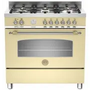
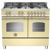 Bertazzoni HER100 6 MFE D CR T
User Manual
Bertazzoni HER100 6 MFE D CR T
User Manual
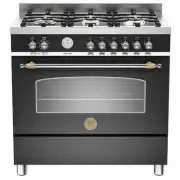
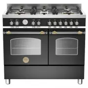 Bertazzoni HER100 6 MFE D NET
User Manual
Bertazzoni HER100 6 MFE D NET
User Manual
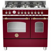
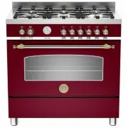
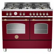 Bertazzoni HER100 6 MFE D VI T
User Manual
Bertazzoni HER100 6 MFE D VI T
User Manual
 Bertazzoni HER100 6 MFE T CR T
User Manual
Bertazzoni HER100 6 MFE T CR T
User Manual
 Bertazzoni HER100 6 MFE T NET
User Manual
Bertazzoni HER100 6 MFE T NET
User Manual
 Bertazzoni HER100 6 MFE T VI T
User Manual
Bertazzoni HER100 6 MFE T VI T
User Manual
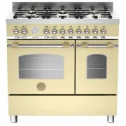
 Bertazzoni HER106L2EAVT
User Manual
Bertazzoni HER106L2EAVT
User Manual
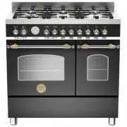
 Bertazzoni HER106L2ENET
User Manual
Bertazzoni HER106L2ENET
User Manual
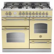
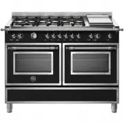
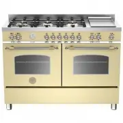 Bertazzoni HER120 6G MFE D CRT
User Manual
Bertazzoni HER120 6G MFE D CRT
User Manual
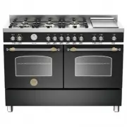 Bertazzoni HER120 6G MFE D NET
User Manual
Bertazzoni HER120 6G MFE D NET
User Manual
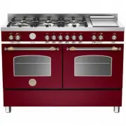 Bertazzoni HER120 6G MFE D VIT
User Manual
Bertazzoni HER120 6G MFE D VIT
User Manual
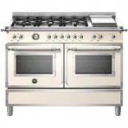 Bertazzoni HER126G2EAVT
User Manual
Bertazzoni HER126G2EAVT
User Manual
 Bertazzoni HER126G2ENET
User Manual
Bertazzoni HER126G2ENET
User Manual
 Bertazzoni HER90 6 HYB S NET
User Manual
Bertazzoni HER90 6 HYB S NET
User Manual
 Bertazzoni HER90 6 MFE D CR T
User Manual
Bertazzoni HER90 6 MFE D CR T
User Manual
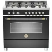
 Bertazzoni HER90 6 MFE D NET
User Manual
Bertazzoni HER90 6 MFE D NET
User Manual
 Bertazzoni HER90 6 MFE D VI T
User Manual
Bertazzoni HER90 6 MFE D VI T
User Manual
 Bertazzoni HER90 6 MFE S CR T
User Manual
Bertazzoni HER90 6 MFE S CR T
User Manual
 Bertazzoni HER90 6 MFE S NET
User Manual
Bertazzoni HER90 6 MFE S NET
User Manual
 Bertazzoni HER90 6 MFE S VI T
User Manual
Bertazzoni HER90 6 MFE S VI T
User Manual