Page 2 - PRODUCT REGISTRATION; TABLE OF CONTENTS
GB - 2 Safety . . . . . . . . . . . . . . . . . . . . . . . . . . . . . . . . . . . . . . 3 Assembly . . . . . . . . . . . . . . . . . . . . . . . . . . . . . . . . . . . 9 Controls and Features . . . . . . . . . . . . . . . . . . . . . . . 11 Operation . . . . . . . . . . . . . . . . . . . . . . . ...
Page 3 - SAFETY
GB - 3 Customer Note: If the Dealer does not register your product, please fill out, sign and return the product registration card to Ariens or go to www.ariens.com on the internet. UNAUTHORIZED REPLACEMENT PARTS Use only Ariens replacement parts. The replacement of any part on this equipment with a...
Page 5 - Danger! To Avoid Serious Injury or Death; SAFETY RULES; Training
GB - 5 5. Danger! To Avoid Serious Injury or Death SAFETY RULES Training Read the Operator’s Manual and other training material. If the operator(s) or mechanic(s) cannot read English, it is the owner’s responsibility to explain this material to them. Become familiar with the safe operation of the eq...
Page 6 - MAINTENANCE AND STORAGE; MOWER SAFETY; Keep Off
GB - 6 Slow down and use caution when crossing roads and sidewalks. Stop blades if not mowing. Be aware of the mower discharge direction and do not point it at anyone. Do not operate the mower under the influence of alcohol or drugs. Use care when loading or unloading the machine into a trailer or t...
Page 7 - During Operation; Operating On Slopes; MAINTENANCE
GB - 7 Do not use starting fluid. Use of starting fluid could damage engine components. Check the brakes and other mechanical parts for correct adjustment and wear. Replace worn or damaged parts promptly. Check the torque on all hardware regularly. Do not wear headphones or listen to music while ope...
Page 8 - Fuel System; Hydraulic System; Tire Maintenance
GB - 8 When making adjustments while the engine is running such as carburetor and motion control linkage adjustments, stand to either side of the tractor and mower and keep clear of moving or rotating components. Allow the Ariens mower time to cool before touching the engine, muffler, or any other p...
Page 9 - Replacement Parts; UNPACK UNIT; Steering Controls; ASSEMBLY
GB - 9 Do not attempt to service a tire unless you have the proper equipment and experience to perform the job. If you are not qualified to make the repairs, take the unit to your Ariens dealer or a qualified repair service. When seating tire beads on the rims, never exceed 2, 4 bar (35 p.s.i.) or t...
Page 11 - CONTROLS AND FEATURES
GB - 11 1. Deck Transport Lock Lever 2. Deck Height Adjustment Dial 3. Control Panel 4. Steering Control Levers 5. Deck Lift Lever 6. Deck Level Adjust CONTROLS AND FEATURES Figure 5 1 2 3 4 5 6 OE3241
Page 12 - Safety Interlock System; CONTROL PANEL; OPERATION
GB - 12 CONTROLS AND FEATURES See figure 5 on page 11 for Controls and Features locations. Safety Interlock System Perform the following tests to ensure the safety interlock system is working properly. If the unit does not perform as stated, contact your Dealer for repairs. 1. Try to start the power...
Page 14 - Fuel; Mounting and Dismounting Safely
GB - 14 OPERATION Break-in Period • Operation of the mower within the first fifty hours can be a major factor in determining the performance and life of the engine and power unit. • The engine may be operated at full RPM, but excessive load should be avoided. If engine begins to slow, due to excessi...
Page 15 - STARTING AND SHUT OFF; Cold Weather Starting; MOWING
GB - 15 STARTING AND SHUT OFF To start the engine: 1. Sit properly in the seat, make sure the steering controls are in the park position and the PTO is off. 2. If the engine is cold, move the choke to the On position. If the engine is warm, do not use choke. 3. Move the throttle to the 3/4 fast posi...
Page 16 - PARKING
GB - 16 Side-Discharge Mowers The mower has a pinned discharge shield that discharges the clippings out of the side of the deck and onto the ground. Uneven Terrain Pre-plan mowing over uneven terrain so the grass will be dry, minimizing wheel slippage and spinning, which will damage the turf. Before...
Page 17 - MAINTENANCE SCHEDULE
GB - 17 Moving the Unit with the Engine Off If the mower engine stalls and will not restart, the unit can be pushed or towed for short distances with the pump bypass valves open. Do not exceed 5 m.p.h. (8 km/h) when towing. IMPORTANT: The bypass valves must be opened two full turns (maximum) before ...
Page 19 - SERVICE ACCESS; Tipping Seat Forward; LUBRICATION AND MAINTENANCE; Engine Oil Level; SERVICE AND ADJUSTMENTS
GB - 19 SERVICE ACCESS Raise the seat to access the battery and the hydraulic reservoir. Use caution while lifting and make sure the seat is locked in the upright position before beginning service on the mower. Tipping Seat Forward To lower the seat back down, push forward on the seat slightly and p...
Page 20 - Engine Oil Change; HYDRAULIC SYSTEM MAINTENANCE; Changing Hydraulic Fluid
GB - 20 Engine Oil Change Change the engine oil and filter after the first 8 hours of operation. Change the oil each subsequent 100 hours of operation after the initial change. 1. Run the engine to warm the oil. 2. Park the mower on level ground. 3. Stop the engine, put the steering control levers i...
Page 21 - BATTERY MAINTENANCE; Battery
GB - 21 Bleeding/Purging the Hydraulic System IMPORTANT: Air in the hydraulic system is the primary cause of hydraulic pump failures. Following hydraulic system service or repair, the hydraulic system MUST be correctly purged of trapped air before placing the mower back in operation. 1. To bleed the...
Page 22 - Cleaning the Battery; CHARGING THE BATTERY; Battery Electrolyte First Aid; CASTERS; Servicing the Caster Pivot Bearings
GB - 22 2. Install the positive battery cable to the positive post on the battery. 3. Install the negative battery cable to the negative post on the battery. 4. Secure the cables by inserting a 1/4-20 x 5/8" carriage bolt through the battery post and through the battery cable. Secure it with a 1...
Page 24 - DRIVE ADJUSTMENTS
GB - 24 5. Set both of the outside blades to be perpendicular to the mower as shown in figure 18. 6. Measure the height of the blade tips on both 1 and 2 and adjust the front adjustment bolts (see figure 17, item 14) and the rear U-bolts to ensure the deck is level from left to right. 7. Rotate the ...
Page 25 - FUEL SYSTEM SERVICE
GB - 25 The Unloader Valve (1) will allow for the removal of fine dirt and dust from the canister body (3) without disassembly. While in operation, this valve will suck closed at 1/3 to 1/2 throttle. • With the engine shut off, squeeze the valve by hand to release dust and debris. • In very dusty op...
Page 28 - Drive Belt Removal and Installation
GB - 28 IMPORTANT: When sharpening blades, be sure to grind the same amount on each side. Unbalanced blades will cause excessive vibration and could cause the spindles to wear prematurely. Check the blade balance by inserting a horizontal rod through the center hole of the blade. The heavy side of t...
Page 29 - Pump Belt Removal and Installation; SHORT TERM; TO TAKE THE UNIT OUT OF STORAGE; STORAGE
GB - 29 7. Reinstall the drive belt idler pulley standoff arm, ensuring the rod end is inserted in its bracket near the clutch. Lightly lubricate the pivot bushings with MP Lithium grease, install and retain with the removed 3/8-16" fasteners. 8. Reinstall or reconnect the drive belt according t...
Page 30 - TROUBLESHOOTING; PROBLEM
GB - 30 TROUBLESHOOTING PROBLEM PROBABLE CAUSE CORRECTION Excessive Vibration 1. Loose spindle/blade fasteners. 2. Blade interference with grass buildup in deck. 3. Blades out of balance. 4. Blade(s) broken or worn badly. 5. Engine mounting bolts are loose. 6. Engine/Idler/Blade pulley loose. 7. Eng...
Page 34 - SPECIFICATIONS
GB - 34 SPECIFICATIONS Model Number 992807 992808 Model ProZoom 2760S ProZoom 3166S Engine Kawasaki Engine Model Number FX751V F850V Engine Displacement - Cu. In. (cc) 52 (852) Maximum Recommended RPM 3600 Liquid or Air Cooled Air Speed Forward Maximum – MPH (k/h) 9 (14.5) Reverse Maximum – MPH (k/h...
Page 35 - NOTES
Page 36 - Limited Lifetime Warranty on Mower Deck Shell; To obtain warranty service, the original purchaser must:; Two-Year Limited Lawn and
ARIENS COMPANY GRAVELY ® | STENS ® | LOCKE ® | NATIONAL ® | BYNORM ® | EVERRIDE ® | GREAT DANE ® Com_Lawn_2008 36 Ariens Company (Ariens) warrants to the original purchaser that Ariens and Gravely brand products manufactured by Ariens, designated or labeled commercial products by Ariens, and sold af...
Page 37 - Limitations; Exclusions – Items Not Covered by This Warranty; Disclaimer
ARIENS COMPANY GRAVELY ® | STENS ® | LOCKE ® | NATIONAL ® | BYNORM ® | EVERRIDE ® | GREAT DANE ® Com_Lawn_2008 37 To find an Ariens or Gravely authorized service representative, contact Ariens at: 655 W. Ryan Street Brillion, WI 54110 (920) 756 - 2141 www.ariens.com www.gravely.com Limitations • Bat...
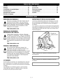
Page 38 - TABLE DES MATIÈRES
F - 2 Sécurité . . . . . . . . . . . . . . . . . . . . . . . . . . . . . . . . . . . . 4 Montage . . . . . . . . . . . . . . . . . . . . . . . . . . . . . . . . . . . 10 Commandes et caractéristiques . . . . . . . . . . . . . . . 12 Fonctionnement . . . . . . . . . . . . . . . . . . . . . . . . . . ...
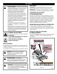
Page 40 - SYMBOLE DE SÉCURITÉ; MOTS D’ALERTE; NOTATIONS; SÉCURITÉ
F - 4 SYMBOLE DE SÉCURITÉ Ce sont des symboles de sécurité. Ils signifient: •ATTENTION!•LA SÉCURITÉ PERSONNELLE EST EN JEU !Lorsque ce symbole est visible : •FAIRE PREUVE DE PRUDENCE !•OBÉIR AU MESSAGE ! MOTS D’ALERTE Les symboles de sécurité ci-dessus et les termes de mise en garde ci-dessous sont ...
Page 41 - CONSIGNES DE SÉCURITÉ; Formation
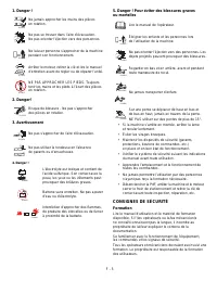
F - 5 1. Danger ! 2. Danger! 3. Avertissement 4. Danger ! 5. Danger ! Pour éviter des blessures graves ou mortelles CONSIGNES DE SÉCURITÉ Formation Lire le manuel d’utilisation et le matériel de formation disponible. Si l’/les opérateur/s ou le/les mécanicien/s ne connaît/connaissent pas la langue, ...
Page 42 - ENTRETIEN ET REMISAGE
F - 6 Ne jamais laisser des enfants ou des personnes non expérimentées utiliser la machine ou s’occuper de son entretien. Des réglementations locales pourraient limiter l’âge de l’opérateur. Le propriétaire/l’utilisateur peut prévenir les accidents ou les blessures survenant sur soi ou sur les autre...
Page 43 - Eviter
F - 7 Débrancher la batterie ou déposer le fil de la bougie avant d’entreprendre toute réparation. Débrancher d’abord la borne négative puis celle positive. Rebrancher d’abord la borne positive puis celle négative. Prendre garde lors du contrôle des lames. Emballer la/les lame/s ou porter des gants ...
Page 44 - Pendant l’utilisation; Utilisation de la machine sur des pentes; ENTRETIEN
F - 8 Ne pas porter de vêtements amples pouvant se coincer dans les parties en mouvement. Ne pas utiliser la machine en short. Veiller à toujours porter des vêtements de travail qui protègent. Il est conseiller de porter des lunettes et des chaussures de sécurité. Il est conseiller de porter des pro...
Page 45 - Alimentation à essence; Circuit hydraulique
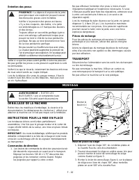
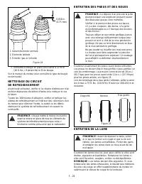
F - 9 Faire refroidir la tondeuse Ariens avant d’intervenir sur le moteur, l’échappement ou toute autre partie pouvant être brûlante. Toujours arrêter le groupe moteur, tourner la PdF et faire refroidir la machine avant de faire l’appoint de carburant. Eliminer l’herbe, les feuilles, la graisse et l...
Page 46 - TRANSPORT; Commandes de direction; MONTAGE
F - 10 Entretien des pneus Veiller à ce que les pneus soient gonflés à la bonne pression. Ne pas gonfler les pneus à une pression supérieure à celle recommandée. Veiller à ce que la visserie, notamment les boulons et écrous de roue soient serrés au couple indiqué. Lors de la dépose d’un pneu du grou...
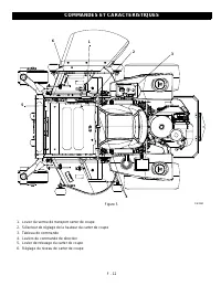
Page 48 - COMMANDES ET CARACTÉRISTIQUES
F - 12 1. Levier du verrou de transport carter de coupe 2. Sélecteur de réglage de la hauteur du carter de coupe 3. Tableau de commande 4. Leviers de commande de direction 5. Levier de relevage du carter de coupe 6. Réglage du niveau de carter de coupe COMMANDES ET CARACTÉRISTIQUES Figure 5 1 2 3 4 ...
Page 49 - Système de verrouillage de sécurité; FONCTIONNEMENT
F - 13 COMMANDES ET CARACTÉRISTIQUES Voir les emplacements des commandes et les caractéristiques en figure 5 à la page 12. Système de verrouillage de sécurité Effectuer les tests suivants pour s’assurer du bon fonctionnement du système de verrouillage de sécurité. Si l’appareil ne fonctionne pas com...
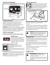
Page 50 - TABLEAU DE COMMANDE
F - 14 TABLEAU DE COMMANDE Contacteur d’allumage Faire fonctionner le contacteur d’allumage avec la clé amovible. Le contacteur a trois positions : Arrêt (1), Marche (2), Démarrage (3). Pour démarrer, tourner la clé sur Démarrage puis relâcher pour aller sur Marche. Pour arrêter le moteur, tourner l...
Page 52 - Mise en marche avec temps froid
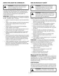
F - 16 INSPECTION AVANT DE COMMENCER L’opérateur est responsable de l’utilisation sûre de la machine. L’opérateur DOIT être familiarisé avec la tondeuse et les commandes du groupe moteur, avec leur fonctionnement et avec toutes les consignes de sécurité AVANT de commencer à travailler. IMPORTANT : I...
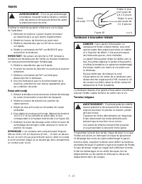
Page 53 - TONTE; Tondeuses à évacuation latérale
F - 17 TONTE N’utiliser la machine qu’après s’être assis sur le siège de l’opérateur. 1. Démarrer la machine. Laisser tourner le moteur au ralenti jusqu’à ce qu’il tourne régulièrement. 2. Mettre les leviers de direction au point mort. 3. Mettre la manette des gaz au 3/4 de sa course sur rapide. 4. ...
Page 54 - STATIONNEMENT; Déplacement de la machine avec le moteur à l’arrêt
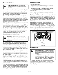
F - 18 Évacuation de l’herbe Le carter de coupe a été conçu pour permettre un flux d’air maximum pour une évacuation d’herbe coupée régulière. En cas de tonte d’herbe haute ou luxuriante, sélectionner une vitesse de déplacement basse ou diminuer la largeur de coupe pour une meilleure évacuation. Pou...
Page 55 - PÉRIODICITÉ DE L’ENTRETIEN
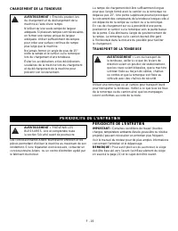
F - 19 CHARGEMENT DE LA TONDEUSE La rampe de chargement doit être suffisamment longue pour que l’angle formé avec le camion ou la remorque ne dépasse pas 15°. Une pente supérieure pourrait provoquer le coincement des composants de la tondeuse lorsque celle-ci est déplacée de la rampe au camion ou à ...
Page 57 - ACCÈS À L’ENTRETIEN; Basculement du siège en avant; GRAISSAGE ET ENTRETIEN; Niveau de l’huile moteur; ENTRETIEN ET RÉGLAGES
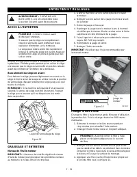
F - 21 ACCÈS À L’ENTRETIEN Relever le siège pour accéder à la batterie et au réservoir hydraulique. Prendre garde pendant qu’on relève le siège et s’assurer que le siège est verrouillé en position relevée avant de commencer l’entretien de la tondeuse. Basculement du siège en avant Pour baisser le si...
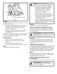
Page 58 - Vidange de l’huile moteur; ENTRETIEN DU SYSTÈME HYDRAULIQUE; Vidange du fluide hydraulique
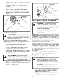
F - 22 5. Monter un filtre neuf en le vissant dans le sens horaire jusqu’à ce que le joint soit en contact avec la surface de montage. Tourner le filtre encore 3/4 de tour à la main. 6. Remettre le bouchon de vidange en place et serrer. 7. Remplir avec de l’huile moteur comme indiqué. 8. Faire tourn...
Page 59 - ENTRETIEN DE LA BATTERIE; Batterie
F - 23 3. Pour vidanger l’huile hydraulique, placer un récipient adéquat sous le filtre hydraulique et déposer celui-ci. 4. Appliquer une fine couche d’huile hydraulique sur le joint du filtre à huile. Avant la remise en place, veiller à ce que la zone soit propre. 5. Mettre le filtre à huile hydrau...
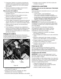
Page 60 - CHARGE DE LA BATTERIE; Démarrage par câble
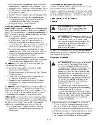
F - 24 5. Faire glisser l’attache en caoutchouc du plateau de la batterie. Décrocher prudemment l’attache et faire glisser l’autre extrémité hors du crochet du plateau de la batterie. 6. Déposer prudemment la batterie. Ne pas toucher les bornes ou toute partie métallique. Mise en place de la batteri...
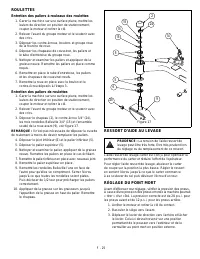
Page 61 - ROULETTES; Entretien des paliers à rouleaux des roulettes; RESSORT D’AIDE AU LEVAGE
F - 25 ROULETTES Entretien des paliers à rouleaux des roulettes 1. Garer la machine sur une surface plane, mettre les leviers de direction en position de stationnement, couper le moteur et retirer la clé. 2. Relever l’avant du groupe moteur et le soutenir avec des crics. 3. Déposer les contre-écrous...
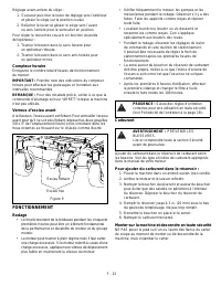
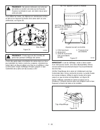
Page 62 - Synchronisation de la hauteur de coupe (Figure 20)
F - 26 4. Si des réglages sont nécessaires, remettre le levier de direction en position intérieure et commencer par tirer vers l’arrière. Dès que ce geste est effectué, l’axe de chape devrait toucher l’extrémité de la fente et entrer en pression sur le ressort. 5. Si des réglages sont nécessaires, d...
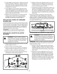
Page 63 - RÉGLAGE DE L’ENTRAÎNEMENT
F - 27 3. Resserrer l’écrou hexagonal 1/2-13" pour le verrouiller en position. 4. Relever le carter de coupe en position de transport et retirer les blocs placés sous le carter. Mesurer de nouveau la hauteur de lame pour s’assurer qu’elle correspond maintenant à la hauteur indiquée par le sélect...
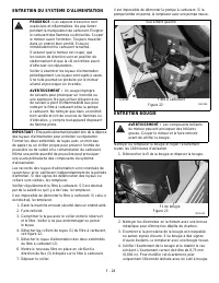
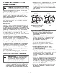
Page 67 - COURROIES; Dépose et pose de la courroie d’entraînement
F - 31 ÉLIMINER L’ACCUMULATION D’HERBE DU CARTER DE COUPE Nettoyer régulièrement la face inférieure du carter pour conserver son efficacité de coupe. Pour accéder à la face inférieure du carter, baisser le levier de la pédale de carter et le verrouiller sur la position de transport. Régler la hauteu...
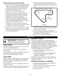
Page 68 - Dépose et pose de la courroie de pompe; COURT TERME; REMISE EN SERVICE DE LA MACHINE; REMISAGE
F - 32 Dépose et pose de la courroie de pompe 1. Veiller à ce que la tondeuse se trouve sur une surface plane et ferme, que la PdF soit désenclenchée, que le moteur soit coupé, que les leviers de direction soient en position de stationnement, que le câble négatif de la batterie soit débranché et que...
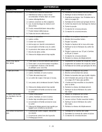
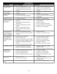
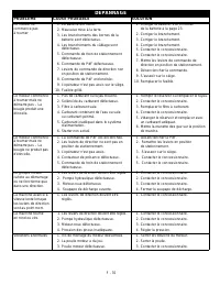
Page 69 - DÉPANNAGE; PROBLÈME
F - 33 DÉPANNAGE PROBLÈME CAUSE PROBABLE SOLUTION Vibrations excessives 1. Visserie broche/lame desserrée. 2. Interférence lame à cause d’une accumulation d’herbe dans le carter. 3. Lames déséquilibrées. 4. Lame/s cassée/s ou très usagée/s. 5. Les vis de montage du moteur sont desserrées. 6. Poulie ...
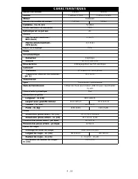
Page 73 - CARACTÉRISTIQUES
F - 37 CARACTÉRISTIQUES Numéro du modèle 992807 992808 Modèle ProZoom 2760S ProZoom 3166S Moteur Kawasaki Numéro de modèle du moteur FX751V F850V Cylindrée – Cu. In. (cc) 52 (852) Tr/min maximum recommandé 3600 Refroidi par air ou par eau Air Vitesse Marche avant maximum – MPH (km/h) 9 (14,5) Marche...
Page 74 - Garantie commerciale; Garantie à vie limitée au carter de la tondeuse
ARIENS COMPANY GRAVELY ® | STENS ® | LOCKE ® | NATIONAL ® | BYNORM ® | EVERRIDE ® | GREAT DANE ® Com_Lawn_2008 38 Garantie commerciale jardinage de deux ans La société Ariens (Ariens) garantit à l’acheteur d’origine que les produits des marques Ariens et Gravely fabriqués par Ariens, désignés ou éti...
Page 75 - Exclusions – Points non couverts par cette garantie; Déni de responsabilité
ARIENS COMPANY GRAVELY ® | STENS ® | LOCKE ® | NATIONAL ® | BYNORM ® | EVERRIDE ® | GREAT DANE ® Com_Lawn_2008 39 Pour connaître un représentant de service Ariens ou Gravely autorisé, contacter Ariens à : 655 W. Ryan Street Brillion, Wisconsin 54110 (920) 756 - 2141 www.ariens.com www.gravely.com Li...


 Ariens 936039
User Manual
Ariens 936039
User Manual
 Ariens 93603800
User Manual
Ariens 93603800
User Manual
 Ariens 915145
User Manual
Ariens 915145
User Manual
 Ariens 991056
User Manual
Ariens 991056
User Manual
 Ariens 91141000 (101-999999)
User Manual
Ariens 91141000 (101-999999)
User Manual
 Ariens 96136000601
User Manual
Ariens 96136000601
User Manual
 Ariens 99107500 (000101)
User Manual
Ariens 99107500 (000101)
User Manual
 Ariens 96136000602
User Manual
Ariens 96136000602
User Manual
 Ariens 96046001100
User Manual
Ariens 96046001100
User Manual
 Ariens 93250400 (101-549)
User Manual
Ariens 93250400 (101-549)
User Manual
 Ariens 936037
User Manual
Ariens 936037
User Manual
 Ariens 99480600 (101-999999)
User Manual
Ariens 99480600 (101-999999)
User Manual
 Ariens 99180000 (101-999999)
User Manual
Ariens 99180000 (101-999999)
User Manual
 Ariens A173K22 (96146000600)
User Manual
Ariens A173K22 (96146000600)
User Manual
 Ariens 91116000 (101-1137)
User Manual
Ariens 91116000 (101-1137)
User Manual
 Ariens A175BG42 (96016002300)
User Manual
Ariens A175BG42 (96016002300)
User Manual
 Ariens 96136000603
User Manual
Ariens 96136000603
User Manual