Amana AGR6603SMS - Manuals
Amana AGR6603SMS Range – User Manual, Troubleshooting Guide in PDF format online.
Manuals:
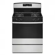
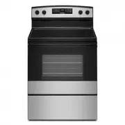
User Manual Amana AGR6603SMS


Summary
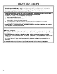
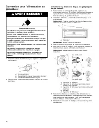
2 RANGE SAFETY WARNING: If the information in these instructions is not followed exactly, a fire or explosion may result causing property damage, personal injury or death. − Do not store gasoline or other flammable vapors and liquids in the vicinity of this or anyother appliance. − WHAT TO DO IF YOU...
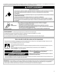
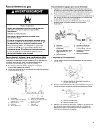
3 WARNING: Gas leaks cannot always be detected by smell. Gas suppliers recommend that you use a gas detector approved by UL or CSA. For more information, contact your gas supplier. If a gas leak is detected, follow the “What to do if you smell gas” instructions. Your safety and the safety of others ...
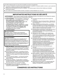
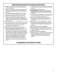
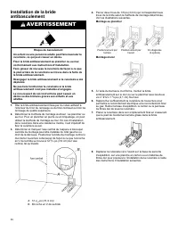
4 IMPORTANT SAFETY INSTRUCTIONS WARNING: To reduce the risk of fire, electric shock, or injury to persons when using the appliance, follow basic precautions, including the following: � WARNING: TO REDUCE THE RISK OF TIPPING OF THE RANGE, THE RANGE MUST BE SECURED BYPROPERLY INSTALLED ANTI-TIP DEVICE...
Troubleshooting Guide Amana AGR6603SMS


Summary
3 Major Appliance Limited Warranty Before contacting us to arrange service, some questions can be addressed without service. Please visit the "Troubleshooting" section at https://www.amana.com/owners for Troubleshooting help. InCanada, visit https://www.amanacanada.ca/owners. HOW TO MAKE A C...
5 Garantie limitée sur le gros appareil ménager Avant de communiquer avec nous pour effectuer un entretien, certains problèmes peuvent être réglés sans notre aide. Veuillez visiter la section « dépannage » du https://www.amana.com/ownerspour obtenir de l’aide. Au Canada, visitez le https://www.amana...
Amana Ranges Manuals
-
 Amana ACR4303MFW
User Manual
Amana ACR4303MFW
User Manual
-
Amana ACR4303MFW
Installation Manual
-
Amana ACR4303MFW
Troubleshooting Guide
-
Amana ACR4303MFW
Manual
-
 Amana ACR4303MMS
User Manual
Amana ACR4303MMS
User Manual
-
Amana ACR4303MMS
Troubleshooting Guide
-
 Amana AEP222VAW
Installation Manual
Amana AEP222VAW
Installation Manual
-
 Amana AER6303MFB
User Manual
Amana AER6303MFB
User Manual
-
 Amana AER6303MFW
User Manual
Amana AER6303MFW
User Manual
-
Amana AER6303MFW
Manual
-
 Amana AER6303MMS
User Manual
Amana AER6303MMS
User Manual
-
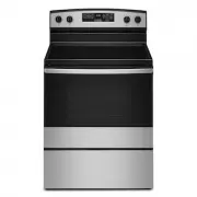 Amana AER6603SMS
User Manual
Amana AER6603SMS
User Manual
-
 Amana AGG222VDW
Installation Manual
Amana AGG222VDW
Installation Manual
-
Amana AGG222VDW
Manual
-
Amana AGG222VDW
Troubleshooting Guide
-
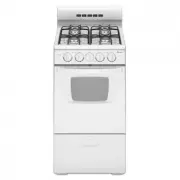
 Amana AGR4203MNW
User Manual
Amana AGR4203MNW
User Manual
-
Amana AGR4203MNW
Installation Manual
-
Amana AGR4203MNW
Manual
-
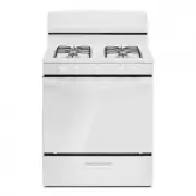
 Amana AGR5330BAS
User Manual
Amana AGR5330BAS
User Manual
-
Amana AGR5330BAS
Installation Manual