Page 2 - Rückfahrkamera-Systems; PRODUKTBESCHREIBUNG; INHALTSVERZEICHNIS
2 3334 45 67 7 101111111112 13 13 14 14 8.0 GARANTIE UND SERVICE 7.0 ENTSORGUNG 6.0 TECHNISCHE DATEN 5.1 Reinigung, Wartung und Aufbewahrung 5.0 WARTUNG UND PFLEGE 4.1 Montage des 4.2 Montage des Monitors 4.3 Bedienung des Monitors4.4 Menüeinstellungen des Monitors4.5 Testen des Rückfahrkamera-Syste...
Page 3 - Bestimmungsgemäßer Gebrauch; . Durch die eingebaute
3 Das Rückfahrkamera-System RV 3.5 ist aus-schließlich für eine zusätzliche Verbesserung der Sichtverhältnisse bei kurzzeitigem Rückwärts-fahren mit einem Kraftfahrzeug bestimmt. Das Rückfahrkamera-System RV 3.5 entbindet Sie nicht von der Beachtung der Verkehrsvorschriften,der Straßenverkehrsordnun...
Page 4 - Allgemeine Sicherheitshinweise
4 ° 2.1.9 nur dann, wenn keine Beschädigungen und Funk-tionsstörungen am Gerät oder an den Kabeln vorhanden sind! Betreiben Sie das Rückfahrkamera-System 2.1.8 Sorgen Sie dafür, dass sich das Gerät im-mer in einer sicheren Umgebung befindet. Setzen Sie das Gerät keinen mechanischen Belastungen, extr...
Page 7 - Schritt 2: Öffnung für das Kamerakabel; Achten Sie darauf, dass; Schritt 1: Nummernschild entfernen; Aufgrund von verschiedenen techni-
7 DE 1 2 34 5 6 7 8 9 3.2 Produktübersicht Kamera mit 7 Infrarot-LEDs und Anschluss-kabel mit Stecker zur Verbindung mit dem Sendegerät Monitorkabel mit 12 V Stecker für den Anschluss am Zigarettenanzünder inkl. 1 A (Ampere) SicherungLCD - Monitor 3,5 " (8,9 cm) Kabelbinder zur Befestigung des S...
Page 8 - Die Positionierung der Kamerahalte-; Schritt 5: Befestigung des Kennzeichens
8 Schritt 4: Befestigung der Kamera Führen Sie den Stecker des Kamerakabels durch den Kunststoffring in den Innenraum des Fahrzeugs bzw. Kofferraumdeckels. Montieren Sie die Kamera mit einem gleichmäßigen Seitenabstand auf die Kamerahalterungen (siehe Bild 4). Verwenden Sie zum Befestigen die beiden...
Page 9 - mitters anschließen; Vor dem Arbeiten am Fahrzeugstrom-
9 DE Schritt 7: Versorgungskabel des Trans- mitters anschließen Nehmen Sie die Abdeckung der Rückfahrleuchte ab. Entfernen Sie die Lampenfassung aus dem Rücklichtgehäuse. Suchen Sie die Kabelzulei-tungen des Fahrzeugs zur Rückfahrleuchte. Beachten Sie hierzu das Handbuch des Fahrzeug-herstellers. Ac...
Page 10 - für Parksperre eingelegt sein. Stellen; Montage des Monitors; Die Positionierung des
Schritt 8: Transmitter befestigen Entfernen Sie die Schutzfolie des Klebebandes auf der Oberseite des Transmitters und kleben Sie diesen hinter der Kofferraumverkleidung an einergeschützten Stelle fest. Befestigen Sie den Trans-mitter zusätzlich mit zwei Kabelbindern . Achten Sie darauf, dass sich k...
Page 11 - Drücken Sie im Modus
DE 4.5 Testen des Rückfahrkamera-Systems 11 4.4 Menüeinstellungen des Monitors Richtlinien On / Off Richtung Farbe Kontrast Helligkeit Sprache English / German Exit Bild 14 4.3 Bedienung des Monitors Ein / Aus Taste, leuchtet blau auf, wenn der Monitor eingeschaltet istMenütaste zum Anwählen des jew...
Page 12 - V Stecker; Mögliche Ursachen
12 4.7 Fehlersuche Die Zündung des Fahrzeugs und der Monitor sind eingeschaltet, zusätzlich ist der Rückwärtsgang eingelegt, aber das Display bleibt dunkel. Die blaue LED leuchtet nicht. Der 12 V Stecker des Monitor-kabels wurde nicht in den Zigarettenanzünder oder eine 12 V Buchse des Fahrzeugs ein...
Page 13 - Aufbewahrung
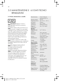
DE 13 6.0 TECHNISCHE DATEN 5.1.4 Lagern nicht bei extremen Temperaturschwankungen! Hierbei entstehendes Kondenswasser kann die Elektronik beschädigen! Sie das Rückfahrkamera-System 5.1.3 kamera-System nur in trockener Umgebung! Feuchtigkeit kann die Elektronik des Rückfahr-kamera-Systems beschädigen...
Page 14 - Kopie des Kassenzettels mit dem Kaufdatum.
14 Wenden Sie sich bei Beschädigungen, Repara-turen oder anderen Problemen mit dem Produkt an die Verkaufsstelle oder qualifiziertes Fach-personal. Die allgemeinen Garantiebedingungen beziehen sich auf Produktions- und Materialdefekte. Bringen Sie ein fehlerhaftes Produkt zur Verkaufs-stelle zurück....
Page 15 - TABLE OF CONTENTS
16161617 17 18 1920 20232424242425 26 26 27 27 8.0 WARRANTY AND SERVICE 7.0 DISPOSAL 6.0 TECHNICAL SPECIFICATIONS 5.1 Cleaning, maintenance and storage 5.0 MAINTENANCE AND CARE 4.1 Installing the backup camera system4.2 Installing the monitor4.3 Monitor operation4.4 Monitor menu settings4.5 Testing ...
Page 17 - General safety instructions; INSTRUCTIONS
2.1.9 Do not operate the backup camera system if the equipment or cables exhibit damage or malfunctions! 2.1.8 Be sure the equipment is always located in a safe environment. Do not expose the device to mechanical stress, extreme temperatures, moisture or vibrations! 2.1.7 Depending on ambient condit...
Page 18 - before each functionality test; of the; Attention – risk of; Risk of electrical
2.2.6 Only install the backup camera system in a safe environment! Keep clothing, hair, limbs and the backup camera system away from moving and hot engine- and car parts! 2.2.3 Always follow safety instructions if thevehicle is on jacks or a car lift or the like! 2.2.2 Do not run or start the vehicl...
Page 19 - Risk of short circuits!; Verify the correct
Images and actual product may vary slightly.Subject to change for the purpose of technicaladvances. Accessories not included. Immediately after unpacking check all parts fordamage and verify all parts are present! Do not use the backup camera system if damaged, incorrect on-screen display or if thei...
Page 20 - Step 2: Hole for camera cable; be sure there are no elec-; Image 2; Due to differences in technical and; Image 1
10 3 4 2 1 5 6 7 8 9 11 Step 2: Hole for camera cable Now look for an opening / drill hole near the li-cense plate opening into the interior of the vehicle to feed the connector cable plug of the camera into the interior of the vehicle. For added visibility and easy installation remove the interior ...
Page 21 - The location of the camera brackets
5 6 9 1 Step 6: Running the camera cable Now run the camera cable to establish a con-nection with the cable of the radio transmitterin the vehicle‘s interior / cavity. Be sure the cables aren‘t pinched or knotted. Now connect the plug from the camera cable to the socket of the radio transmitter . Th...
Page 22 - Image 9; Disconnect the negative cable from the
Caution! If you are unfamiliar with the I installation and the connections or are unsure with one of these steps, please consult a specialist regarding the installation!There is a risk of property damage or personal injuries! Using the second cable clamp connect the vehicle‘s 12 V - (negative) rever...
Page 24 - Testing the backup camera system
14 12 13 15 16 17 ▪ First engage the hand brake and be sure thevehicle is not in gear. On vehicles with auto-matic transmission put the car into “P“ for parking lock. Turn the ignition to II, do not startthe engine! ▪ Plug in the monitor by plugging the monitor cable into the 12 V vehicle outlet. Pr...
Page 25 - Possible causes
The vehicle ignition and the monitor are switched on and the car is in reverse but the display remains dark. The blue LEDdoesn‘t light up. The 12 V monitor cable plugis not plugged into the vehicle‘scigarette lighter or a 12 V outlet. Plug the 12 V monitor cableplug into the cigarette lighteror a 12...
Page 26 - Transmitter
Device designation: backup camera systemRV 3.5 Item number: 97152 Service and operating -10 C to + 50 Ctemperature: (Celsius) Backup speed: max. 3 km/h (kilometers per hour) Transmission range: max. 10 m (meters) Monitor: Diagonal screen size: 3.5 " / 8.9 cm Resolution: 320 x 240 pixel Dimension...
Page 27 - Copy of the receipt showing the purchase date.
Please contact the point of sale or qualifiedspecialists for damage, repairs or other issues with the product. The general warranty terms apply to defects in production and materials. Please return defective products to the point of sale. For speedy processing of your warranty claimyou will also nee...
Page 28 - SOMMAIRE
28 29292930 3031 3233 333637373737 38 39 39 40 40 8.0 GARANTIE ET SERVICE APRÈS-VENTE 7.0 ÉLIMINATION 6.0 CARACTÉRISTIQUES TECHNIQUES 5.1 Nettoyage, maintenance et entretien 5.0 MAINTENANCE ET ENTRETIEN 4.1 Montage du système de caméra de recul4.2 Montage de l ' écran 4.3 Utilisation de l ' écran 4....
Page 29 - Utilisation conforme
29 F Le système de caméra de recul RV 3.5 a étéconçu exclusivement pour améliorer la vision lors-que l ' on roule brièvement en marche arrière avec un véhicule. Le système de caméra de recul RV 3.5 n ' exempte pas du respect des règles de conduite, du code de la route et de l ' obligation à la prude...
Page 30 - Consignes générales de sécurité; DE SÉCURITÉ
▪ Permet une meilleure visibilité derrière le véhicule, pour une plus grande sécurité ▪ Transmission radio sans fil, encodée 2,4 Ghz ▪ Fonction vision de nuit ▪ Grand angle de vue (110 ) ▪ Lignes de distance pour les obstacles ▪ Menus pratiques d ' utilisation ▪ Idéal pour voitures, camping-cars et ...
Page 31 - chaque test de fonctionnement
2.2.4 Attention ! Risque en raison de la tension électrique dans les bobinesd ' allumage, la trappe distributrice, les câbles et bougies d ' allumage et les composants électriques ! 2.2.5 Observez les consignes de sécurité et le manuel du fabricant du véhicule ! 2.2.3 Respectez les consignes de sécu...
Page 32 - emballage
32 Les illustrations peuvent diverger légèrement du produit. Sous réserve de modifications servant au progrès technique. Décoration non fournie. Lorsque vous déballez les pièces, contrôlez qu ' elles soient toutes là et non endommagées ! N ' utilisez pas l ' appareil en cas de dommages, si l ' affic...
Page 34 - Etape 3 : Fixer les supports de la caméra
5 6 9 1 Étape 6 : Poser le câble de caméra Placez ensuite le câble de la caméra pourconnecter le câble à l ' émetteur dans l ' habi- tacle / le coffre du véhicule. Veillez à ce que le câble ne soit pas pincé et ne présente aucun nœud. Connectez ensuite la prise du câble de la caméra avec la prise fe...
Page 37 - Changer le fusible
14 12 13 15 16 17 Guidelines On / Off Direction Colour Contrast Brightness Language English / German Exit ▪ Avec les touches ( + ) et ( - ) , vous pouvez augmenter, réduire ou activer les para-mètres suivants :Clarté : Régler la clarté de l ' écran Contraste : Régler le contraste de l ' écran Couleu...
Page 38 - erreurs
38 Le véhicule est démarré et l ' écran est allumé, la marche arrière est enclenchée mais l ' écran reste noir. La LED bleue ne s ' allume pas. La prise 12 V du câble de l ' écran n ' a pas été branchée à l ' allume- cigare ou à la prise femelle 12 Vdu véhicule. Branchez la prise 12 V du câble de l ...
Page 39 - entretien
Désignation de l ' article : Système de caméra de recul RV 3.5 Référence : 97152 Température de service - 10 C à + 50 Cet de travail : (Celsius) Vitesse de marche max. 3 km/h arrière : (kilomètre par heure) Portée de transmission : max. 10 m (mètres) Écran : Diagonale de l ' écran : 3,5 " / 8,9 ...
Page 41 - INDICE
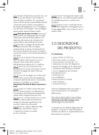
42424243 4344 4546 46495050505051 52 52 53 53 8.0 GARANZIA E ASSISTENZA 7.0 SMALTIMENTO 6.0 DATI TECNICI 5.1 Pulizia, manutenzione e custodia 5.0 MANUTENZIONE E RIPARAZIONI 4.1 Montaggio del sistema video per retromarcia4.2 Montaggio del monitor4.3 Uso del monitor4.4 Impostazioni menù del monitor4.5...
Page 43 - Avvertenze generali di sicurezza
2.1.9 Usare il sistema video solo se non sono presenti danni o disturbi al funzionamento del dispositivo o dei cavi. 2.1.8 Assicurarsi che il dispositivo si trovi sempre in un ambiente sicuro. Non sottoporlo a carichi meccanici, temperature estreme, umidità escossoni. 2.1.7 A seconda delle condizion...
Page 45 - Pericolo di corto circuito!
Le immagini possono differire leggermente dal prodotto. Ci riserviamo il diritto di apportare modifiche che offrano un miglioramento tecnico. Decorazione non compresa. Verificare direttamente dopo aver aperto il pacco eventuali danni e la completezzadella fornitura. Non usare il sistema video in cas...
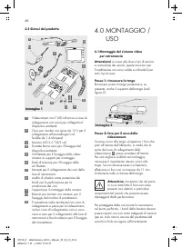
Page 47 - Passo 3: fissare i supporti per
5 6 9 1 Passo 6: collocare il cavo per videocamera Collocare ora il cavo per la videocamera , per collegarlo al cavo del trasmettitore radio nell ' abitacolo del veicolo. Assicurarsi che i cavi non siano incastrati o annodati. Collegare ora la spina del cavo per la videocamera con la bussola del tra...
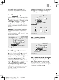
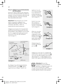
Page 48 - Immagine 9; Immagine 7; Passo 7: collegare il cavo di alimentazione; uso del produttore del veicolo.
Attenzione! Se non si ha dimestichezza con le installazionielettriche e i collegamenti, oppure non si è sicuri di uno di questi passi, chiedere consiglio ad esperti nel settore delle installazioni. Sussiste il pericolo di danni a cose e persone. Collegare ora il cavo da 12 V - (negativo) del veicolo...
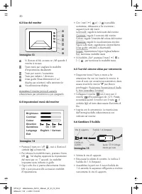
Page 50 - Cambiare il fusibile
14 12 13 15 16 17 Guidelines On / Off Direction Colour Contrast Brightness Language English / German Exit ▪ Svitare la vite di supporto. ▪ Rimuovere la calotta di contatto, la molla e ilfusibile da 1 A (Ampere). ▪ Assemblare le parti con il nuovo fusibile da 1 A secondo la sequenza raffigurata e avv...
Page 51 - Possibili cause
L ' auto e il monitor sono accesi, inoltre è inserita la retromarcia,ma il display rimane spento. Il LED blu non si accende. La spina da 12 V del cavo per il monitor o la bussola da 12 V del veicolo non sono stateinserite. Inserire la spina da 12 V del cavo per il monitor o una bussola da 12 V del v...
Page 54 - OBSAH
55555556 5657 5859 59626363636364 65 65 66 66 8.0 ZÁRUKA A SERVIS 7.0 LIKVIDACE DO ODPADU 6.0 TECHNICKÉ ÚDAJE 5.1 Čištění, údržba a skladování 5.0 ÚDRŽBA A OŠETŘOVÁNÍ 4.1 Montáž couvacího kamerového systému4.2 Montáž monitoru 4.3 Obsluha monitoru4.4 Menu pro nastavení monitoru4.5 Testování couvacího...
Page 55 - Použití k určenému účelu; VOD
Couvací kamerový systém RV 3.5 je určenvýhradně pro dodatečné zlepšení viditelnosti při krátkém couvání s motor - ovým vozidlem. Couvací kamerový systém RV 3.5 Vásnezbavuje povinnosti dodržovat dopravnípředpisy, pravidla silničního provozu anipovinnosti zabránit ohrožení bezpečnosti.Kamera je určena...
Page 56 - BEZPEČNOS
2.1.9 Používejte couvací kamerový systémjen není-li poškozený, nemá poruchy rádiového přenosunebo poškozené kabely! 2.1.8 Dbejte na to, aby se přístrojnacházel vždy v bezpečném prostředí. Nevystavujte ho mechanickému zatížení, extrémním teplotám, vlhkosti a otřesům! 2.1.7 V závislosti na podmínkách ...
Page 60 - Obrázek 4
5 6 9 1 Krok 6: Zavedení kabelu kamery Zaveďte kabel kamery , pro spojení s kabelem vysílače v dutině nebo uvnitř vozidla. Dbejte přitom na to, aby nebyly kabely uskřípnuté nebo zauzlované. Nyní nastrčte zástrčku kabelu kamery do zdířky vysílače . Obrázek 6 Krok 5: Připevnění státní poznávací značky...
Page 63 - Testování couvacího kamerového
14 12 13 15 16 17 Guidelines On / Off Direction Colour Contrast Brightness Language English / German Exit ▪ Vyšroubujte přidržovacící šroub. ▪ Vyjměte čepičku kontaktu, pružinu apojistku 1 A (Ampér) ▪ Sestavte všechny díly spolu s novou pojistkou 1 A podle zobrazeného pořadí zase dohromady a zašroub...
Page 64 - Možné příčiny
Zapalování vozidla a monitor jsou zapnuté,přídavně byla zařazena zpátečka, ale displej zůstává tmavý. Modrá LED nesvítí. Zástrčka napájecího kabelu pro monitor na 12 V není za - strčená do zdířky cigare to- vého zapalovače nebo do jiné zdířky na 12 V ve ozidle. Zastrčte zástrčku na 12 V napájecího k...
Page 66 - ODPADU
Při problémech, poškození nebo pro opravy výrobku se obraťte na prodejnunebo na kvalifikovaný, odbornýpersonál. Všeobecné záruční podmínky se vztahujína chyby výroby a vady materiálu. Vadný výrobek zaneste zpátky do prodejny. Pro rychlé zpracování Vaší reklamacepotřebujete: ▪ kopii pokladního lístku...
Page 69 - Všeobecné bezpečnostné pokyny; BEZPEČNOST; Charakteristika výbavy cúvacieho
° 2.1.9 Používajte cúvací kamerový systémiba vtedy, ak sa na prístroji alebo nakábloch nevyskytujú žiadnepoškodenia! 2.1.8 Zabezpečte, aby sa prístroj vždynachádzal v bezpečnom prostredí.Nevystavujte ho mechanickej záťaži,extrémnym teplotám, vlhkostia otrasom! 2.1.7 Závisle od okolitých podmienok je...
Page 71 - Nebezpečenstvo skratu!
Zobrazenia sa môžu minimálne odlišovaťod produktu. Zmeny slúžiace tech-nickému pokroku vyhradené. Dekorácie nie sú súčasťou dodávky. Ihneď po vybalení skontrolujte všetkyčasti ohľadom prípadných poškodení akompletnosti dodávky! Cúvací kamerový systém nepoužívajtev prípade poškodení, chýbajúceho obra...
Page 76 - systému
14 12 13 15 16 17 Guidelines On / Off Direction Colour Contrast Brightness Language English / German Exit 14 12 13 1516 ▪ Vyskrutkujte pridržovaciu skrutku. ▪ Vyberte kontaktný uzáver, pružinu a 1 A (ampér) poistku. ▪ Zložte všetky časti s novou 1 A poistkou podľa uvedeného poradia dokopy a znovu pr...
Page 77 - Možné príčiny; Vyhľadávanie chyby
Zapaľovanie vozidla a monitor sú zapnuté, k tomu je zaradená spiatočka, ale displej ostáva tmavý. Modrá LED nesvieti. 12 V zástrčka kábla monitoranie je zastrčená do zásuvky cigaretového zapaľovača, alebo do 12 V zásuvky vozidla. Zasuňte 12 V zástrčku kábla monitora docigaretového zapaľovača alebo 1...
Page 78 - ROSTLIVOSŤ; časom uvo
Názov prístroja: Cúvací kamerový systém RV 3.5 Číslo výrobku: 97152 Prevádzková a -10 C až + 50 C pracovná t eplota: (Celsius) Rýchlosť spätnej max. 3 km/h jazdy: (kilometer za hodinu) Dosah prenosu: max. 10 m (meter) Monitor: Diagonála 3,5 " / 8,9 cm obrazovky:Rozlíšenie: 320 x 240 pixelov Rozm...


 AEG AREH30LF
User Manual
AEG AREH30LF
User Manual
 AEG AREI20XLF
User Manual
AEG AREI20XLF
User Manual
 AEG FFB72746PM
User Manual
AEG FFB72746PM
User Manual
 AEG PS254DB
User Manual
AEG PS254DB
User Manual
 AEG NIK85M00AZ
User Manual
AEG NIK85M00AZ
User Manual
 AEG DGE5662HB
User Manual
AEG DGE5662HB
User Manual
 AEG DGE5962HB
User Manual
AEG DGE5962HB
User Manual
 AEG HVB95450IB
User Manual
AEG HVB95450IB
User Manual
 AEG PL700
User Manual
AEG PL700
User Manual
 AEG W14120
User Manual
AEG W14120
User Manual
 AEG DC240
User Manual
AEG DC240
User Manual
 AEG T738A4OBC
User Manual
AEG T738A4OBC
User Manual
 AEG T858M6OBC
User Manual
AEG T858M6OBC
User Manual
 AEG T859M6OBC
User Manual
AEG T859M6OBC
User Manual
 AEG T959M6ORS
User Manual
AEG T959M6ORS
User Manual
 AEG IKE95771FB
User Manual
AEG IKE95771FB
User Manual
 AEG AREI9XLF
User Manual
AEG AREI9XLF
User Manual
 AEG A18SPC3
User Manual
AEG A18SPC3
User Manual
 AEG LF7384O4C
User Manual
AEG LF7384O4C
User Manual