Page 2 - INHALTSVERZEICHNIS
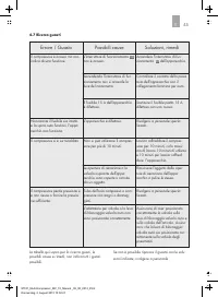
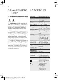
2 3334 457 7 8 999 11121213 14 14 15 15 8.0 GARANTIE UND SERVICE 7.0 ENTSORGUNG 6.0 TECHNISCHE DATEN 5.1 Reinigung, Wartung und Aufbewahrung 5.0 WARTUNG UND PFLEGE 4.7 Fehlersuche 4.6 Sicherung wechseln 4.5 Absaugen mit dem Pumpschlauch (flexiblen Niederdruckschlauch) 4.4 Aufblasen mit dem Pumpschla...
Page 3 - Warnung vor heißer Oberfläche!
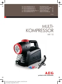
3 DE ° Der Multikompressor MV 10 ist ausschließlich für den privaten Gebrauch bestimmt. Das Gerät ist zum Aufpumpen von PKW-, Motorrad- und Fahr-radreifen und aufblasbaren Sport-, Spiel- und Freizeitartikeln sowie zum Absaugen der Luft aus aufblasbaren Sport-, Spiel- und Freizeitartikeln geeignet. J...
Page 5 - Achtung! Gefahr von Sachschäden; Das Eindringen von Flüssigkeiten in das
5 2.2.7 Achten Sie bei der Benutzung des Gerätesdarauf, dass der Druckluftschlauch und die Kabel nicht durch scharfkantige Gegenstände und Wärmequellen beschädigt werden und knicken Sie diese nicht. Verlegen Sie die Kabel und den Druckluftschlauch so, dass man nicht darüber stolpern kann. Ein beschä...
Page 6 - Blasen Sie keine Schwimm-; Warnung vor explosions-; Klasse 1; Körperverletzung und Sachbeschädigung!; Richten Sie den Druckluftstrahl nicht auf
6 2.2.30 Verwenden Sie keinen beschädigten Ventiladapter! Dieser kann durch den Luftdruck zerbersten. Achtung! Verletzungsgefahr! 2.2.29 Pumpen Sie aus Sicherheitsgründen denArtikel nur in kurzen Aufpumpintervallen auf und prüfen Sie zwischendurch den Luftdruck am Manometer und dem aufzublasenden Ar...
Page 7 - Verhalten bei einem Notfall
DE 7 Abbildungen können geringfügig vom Produktabweichen. Änderungen, die dem technischenFortschritt dienen, vorbehalten. Dekoration nichtenthalten. Verwenden Sie das Gerät nicht bei Beschädi-gung, Fehlfunktionen, oder wenn die Betriebsan-leitung nicht vorhanden oder nicht vollständig ist! Prüfen Si...
Page 12 - Sicherung wechseln
15 16 13 13 12 ▪ Schrauben Sie die Halteschraube heraus. ▪ Entnehmen Sie die Kontaktkappe und die 15 A (Ampere) Rundsicherung. ▪ Setzen Sie alle Teile mit der neuen 15 A Siche-rung gemäß der abgebildeten Reihenfolge zu-sammen und schrauben Sie die Halteschraubewieder auf (siehe Bild 10). Bild 10 Kon...
Page 13 - Mögliche Ursachen
Der Kompressor ist eingeschaltet, zeigt aber keine Funktion. Der Betriebsschalter ist nichteingeschaltet. Schalten Sie den Betriebsschalter des Gerätes ein. Prüfen Sie den Kontakt des Kfz-Steckers des Gerätes mit der Kfz-Steckerbuchse. Beim Einschalten des Betriebs-schalters leuchtet die Manometer-b...
Page 15 - Kopie des Kassenzettels mit dem Kaufdatum.
Wenden Sie sich bei Beschädigungen, Repara-turen oder anderen Problemen mit dem Produkt an die Verkaufsstelle oder qualifiziertes Fach-personal. Die allgemeinen Garantiebedingungen beziehen sich auf Produktions- und Materialdefekte. Bringen Sie ein fehlerhaftes Produkt zur Verkaufs-stelle zurück. Fü...
Page 16 - TABLE OF CONTENTS
16 171717 18 18 1921 2122 23232325262627 28 28 29 29 8.0 WARRANTY AND SERVICE 7.0 DISPOSAL 6.0 TECHNICAL DATA 5.1 Cleaning, maintenance and care 5.0 MAINTENANCE AND CARE 4.7 Troubleshooting 4.6 Replacing fuses 4.5 Deflating with the pump hose (flexible low pressure hose) 4.4 Inflating with the pump ...
Page 17 - Equipment functionality
GB 17 The Multicompressor MV 10 is a portable device with a powerful 2-way compressor. The built-in air hose with automotive valve connector and valve quick disconnect allows you to conveniently inflate car, motorcycle and bicycle tyres, balls, and other items requiring a high air pressure up to 10 ...
Page 19 - Risk of electrical; Attention! Risk of injury and property
19 2.2.7 When using the unit, be sure the air hose and cables will not be damaged by sharp objects or heat sources, and do not bend. Place the ca-bles and compressed air hose so as not to create a tripping hazard. Immediately replace a dam-aged compressed air hose or damaged cables! 2.2.6 Only use t...
Page 23 - Operating the light
23 ° Do not operate the compressor longer than 10 minutes, then allow the unit to cool down for 10 minutes! Car, motorcycle- and bicycle tyres with auto-motive valve (Schrader valve with 7.7 mm thread diameter) can be inflated without adapter! Image 6 Select the desired valve adapter , or . Open the...
Page 26 - Image 9
26 ▪ Unscrew the retaining screw. ▪ Remove the terminal cap and the 15 A(Ampere) round fuse. ▪ Reassemble all parts with the new 15 A fuse inthe order shown and replace the retainingscrew (see Image 10). Image 10 Terminal cap 12 V plugVehicle connector Retaining screw Round fuse 15 A (Ampere) 12 V a...
Page 27 - Possible causes
27 The compressor is switched on but not functioning. The operating switch is notactivated. Activate the unit ' s operating switch . Check the contact between the unit ' s vehicle plug and the vehicle receptacle. When switching on the operating switch the manometer lightdoesn ' t light up. Replace t...
Page 30 - TABLE DES MATIÈRES
30 31313132 323335 3536 37373739404041 42 42 43 43 8.0 GARANTIE ET SERVICE APRÈS-VENTE 7.0 MISE AU REBUT 6.0 CARACTÉRIST. TECHNIQUES 5.1 Nettoyage, maintenance et conservation 5.0 MAINTENANCE ET ENTRETIEN 4.7 Recherche d ' erreur 4.6 Changer le fusible 4.5 Aspirer avec le tuyau de la pompe (tuyau fl...
Page 32 - appareil
32 2.1.10 N ' utilisez pas l ' appareil lorsque celui-ci est tombé ou a été endommagé de quelque autre manière. Apportez-le à un électricien qualifié pour contrôle ou réparation. 2.1.9 L ' appareil ne doit pas être modifié. 2.1.8 Toutes les réparations sur l ' appareil doivent être effectuées par un...
Page 37 - Illustration 6; Lors de l ́u; Utiliser le compresseur
37 Sélectionnez l ' adaptateur de valve souhaité (par ex. ou ou ). Ouvrez la fermeture rapide en appuyant sur le levier de fermeture rapide du tuyau d ' air comprimé . Installez ensuite l ' adaptateur de valve et appuyez sur le levier pour refermer en direction du tuyau d ' air comprimé (voir illust...
Page 38 - Illustration 7
38 ▪ Ouvrez le cache de la valve de l ' article. ▪ Mettez l ' adaptateur de valve adapté avec la fermeture rapide et appuyez celle-ci dans laalve de l ' article. Si l ' adaptateur de valve se dé- tache de la valve pendant le gonflage, vous devez l ' appuyer manuellement sur la valve. ▪ Contrôlez que...
Page 39 - Illustration 8
39 ▪ Contrôlez que l ' adaptateur tient bien dans la valve de l ' article en tirant dessus avec précau- tion. ▪ Enfichez ensuite l ' extrémité libre du tuyau de pompe flexible sur la valve de gonflage ducompresseur. Veillez à ce que cela tienne bien. ▪ Un réglage du marquage de la flèche de labague ...
Page 40 - Fiche
40 Fiche automobile 12 V ▪ Enfichez ensuite l ' extrémité libre du tuyau de pompe flexible sur la valve d ' aspiration du compresseur. Veuillez à ce que cela tienne bien. ▪ Pour mettre en route le compresseur, appuyezsur l ' interrupteur du compresseur dans la posi tion ( I ) . Remarque : le compres...
Page 41 - erreur
41 Le compresseur allumé mais ne fonctionne pas. L ' interrupteur n ' est pas allumé. Allumez l ' interrupteur de service de l ' appareil. Contrôlez le contact de la fiche automobile de l ' appareil avec la prise de la voiture. Lors de la mise en route de l ' interrupteur, l ' éclairage du manomètre...
Page 44 - INDICE
44 45454546 464749 4950 51515153545455 56 56 57 57 8.0 GARANZIA E ASSISTENZA 7.0 SMALTIMENTO 6.0 DATI TECNICI 5.1 Pulizia, manutenzione e conservazione 5.0 MANUTENZIONE E CURA 4.7 Ricerca guasti 4.6 Sostituzione fusibile 4.5 Aspirare con il tubo pompa (tubo flessibile a bassa pressione) 4.4 Pompare ...
Page 50 - insieme del prodotto
Manometro, indica la pressione dell ' aria fino ad un max. di 10 bar / 145,03 PSI (bar e PSI sono unità della pressione, 1 Bar = 14,50 PSI) e illuminazione del quadranteLuce con 4 LED, inclinabile a 180 gradiTubo per l ' aria compressa, ripiegabile nello scomparto inferiore dell ' alloggiamento. Lev...
Page 51 - Figura 6; In; Uso del compressore
▪ Premere l ' interruttore on / off della luce in in posizione ( I ) . La luce con 4 LED è ora accesa. ▪ Girando la testa della lampada potete inclinarla di 180 gradi (vedi fig. 5). ▪ Per spegnere le luci a LED premere l ' inter- ruttore on / off della luce in posizione ( O ) . 51 ° Il compressore p...
Page 54 - Sostituzione fusibile
54 ▪ Svitare la vite di arresto ▪ Togliere la valvola di contatto e il fusibile roton-do 15 A (Ampere). ▪ Montare tutti gli elementi con il nuovo fusibile15 A da sequenza, come rappresentato e ri-avvitare nuovamente la vite d ' arresto (vedi fig. 10). Figura 10 Valvola di contatto Spina di collegame...
Page 55 - Possibili cause
55 Il compressore è acceso ma non indica alcuna funzione. L ' interruttore di funzionamento non è acceso. Accendere l ' interruttore di fun- zionamento dell ' apparecchio. Controllare il contatto della presaauto dell ' apparecchio con il collegamento femmina per auto. Accendendo l ' interruttore di ...
Page 56 - Pulizia, manutenzione e conservazione
56 Descrizione: Multicompressore MV 10 Numero art.: 97181Dimensioni: ca. 24,5 x 13,3 x 21 cm (L x L x A cm)Peso: ca. 1,55 kgFusibile: 15 A (Ampere) Temp. d ' esercizio: 0 C - 50 C (Celsius) Compressore: Prestazioni: max. 10 bar / 145 psi(bar / psi = unità pressione) Indicatore pressione / manometro:...
Page 58 - OBSAH
58 59595960 606163 6364 65656567686869 70 70 71 71 8.0 ZÁRUKA A SERVIS 7.0 ODSTRAN Ě NÍ DO ODPADU 6.0 TECHNICKÁ DATA 5.1 Č išt ě ní, údržba a skladování 5.0 ÚDRŽBA A OŠET Ř OVÁNÍ 4.7 Hledání p ř í č in poruch 4.6 Vým ě na pojistky 4.5 Odsávání s hadicí (pružná nízkotlaká hadice) 4.4 Pumpování hadicí...
Page 60 - ístroje
60 2.1.10 Neuvád ě jte p ř ístroj do provozu, jestliže spadl z výšky nebo byl jinak poškozen. Nechte ho zkontrolovat anebo opravit kvalifikovaným elektriká ř em! 2.1.9 P ř ístroj se nesmí modifikovat (m ě nit). 2.1.8 Opravy p ř ístroje smí provád ě t jen kvalifikovaný elektriká ř nebo kvalifikovaný ...
Page 64 - ňů; Obrázek 3
Manometr, stupnice tlaku do max. 10 bar / 145,03 PSI (bar a PSI jsou jednotky tlaku, 1 bar = 14,50 PSI) a osv ě tlení stupnice manometru Sv ě tlo se 4 LED, oto č né o 180 stup ňů Tlaková hadice, uložitelná do spodní prohlubn ě na t ě lese p ř ístroje Koncovka pro automobilové ventily s rychlouzáv ě ...
Page 65 - ÍSLUŠENSTVÍ; Jestli
▪ Stiskn ě te vypína č osv ě tlení o polohy ( I ). Sv ě tlo se 4 LED se rozsvítí. ▪ Lampu m ů žete natá č et o 180 stup ňů (viz obrázek 5). ▪ Pro vypnutí LED sv ě tla stiskn ě te vypína č osv ě tlení do polohy ( O ). 65 ° Kompresor smí být v provozu jen maximáln ě 10 minut, potom se musí nechat 10 m...
Page 68 - tlakové
68 ▪ Vyšroubujte šroub. ▪ Sejm ě te kontaktní č epi č ku a vyjm ě te kulatou pojistku 15 A (ampéry). ▪ Sestavte zase všechny díly dohromady,spolu s novou pojistkou 15 A, v po ř adí podle obrázku a zašroubujte šroub (vizobrázek 10). Obrázek 10 Kontaktní č epi č ka Zástr č ka na 12 V Š roub Kulatá poj...
Page 69 - ěň; Možné p; Hledání příčin poruch
69 Kompresor je zapnutý, ale bez funkce. Provozní vypína č není zapnutý. P ř ed použitím kompresoru zapn ě te nejd ř íve provozní vypína č . Zkontrolujte kontakt zástr č ky p ř ístroje v zásuvce. P ř i zapnutí provozního vypína č e se nerozsvítí osv ě tlení manometru. Vym ěň te vadnou plochou pojist...
Page 70 - OVÁNÍ
70 ° ° Popis p ř ístroje: Multikompresor MV 10 Čí slo artiklu: 97181 Rozm ě ry: cca 24,5 x 13,3 x 21 cm (D x Š x V cm)Váha: cca 1,55 kg Pojistka p ř ístroje: 15 A (ampéry) Provozní teplota: 0 C - 50 C (Celsia) Kompresor: Výkon kompresoru: max. 10 bar / 145 psi(bar / psi = jednotkatlaku) Zobrazení tl...
Page 74 - Všeobecné bezpečnostné pokyny; NÉ POKYNY; Vybavenie prístroja
74 2.1.10 Nepoužívajte prístroj, ak spadol alebo bol iným spôsobom poškodený. Prineste ho na preskúšanie alebo opravu kvalifikovanému elektrikárovi! 2.1.9 Prístroj nesmie by ť modifikovaný (zmenený). 2.1.8 Všetky opravy na prístroji musí vykona ť kvalifikovaný elektrikár / kvalifikovaný odborný pers...
Page 77 - Čo robiť v nú
77 Zobrazenia sa môžu mierne odlišova ť od produktu. Zmeny slúžiace technickému pokroku vyhradené. Dekorácia nie je sú č as ť ou dodávky. V prípade poškodení, chybových funkcií alebo chýbajúceho č i neúplného návodu na používanie prístroj nepoužívajte! Ihne ď po rozbalení skontrolujte všetky č asti ...
Page 78 - Prehľad o produkte; Obrázok 3
Manometer, ukazovate ľ tlaku vzduchu do. 10 bar / 145,03 PSI (bar a PSIsú jednotky tlaku, 1 Bar = 14,50 PSI)a osvetlenie č íselníka Svietidlo s 4 LED-kontrolkami, otá č ate ľ né o 180 stup ň ov Pneumatická hadica uskladnite ľ ná na spodnom preh ĺ bení schránky Pá č ková zástr č ka autoventilu s rých...
Page 83 - Vyhľadávanie chyby
83 Kompresor je zapnutý, ale nevykazuje žiadnu funkciu. Prevádzkový spína č nie je zapnutý. Zapnite prevádzkový spína č prístroja. Skontrolujte kontakt automobilovej zástr č ky prístroja s automobilovouzásuvkou. Pri zapnutí prevádzkového spína č a sa osvetlenie manometra nerozsvietilo. Nahra ď te po...