Page 2 - Downloaded from
2 Dear Customer, Thank you for buying a BLANCO Freestanding Cooker. Before we continue telling you about this oven, we cordially invite you to become part of the Blanco family by subscribing online. Please visit our website where you can easily register for product/cooking demonstrations, and reques...
Page 3 - OPERATE THIS APPLIANCE BEFORE READING THE; DO NOT; PLACE ARTICLES ON OR AGAINST THIS APPLIANCE; DO NOT; STORE CHEMICALS OR FLAMMABLE MATERIALS OR; DISPOSAL INFORMATION
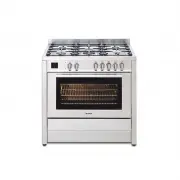
3 READ THE INSTRUCTION BOOKLET BEFORE INSTALLING AND USING THE APPLIANCE. It is important that you retain these instructions, proof of purchase as well as other important documents about this product for future reference. The manufacturer will not be responsible for any damage to property or to pers...
Page 5 - PRODUCT DESCRIPTION; Stainless steel kick plate
5 PRODUCT DESCRIPTION The following is a brief overview of all features that are evident in this product. - Square stainless steel design - 6 burner configuration including Dual Control triple ring wok burner: • 1 x auxiliary burner(4.2 Mj/h ULPG / 4 Mj/h NG) • 3 x semi rapid burners(7.6 Mj/h ULPG /...
Page 7 - FIG. 1
7 Any walls of the adjacent furniture pieces and the wall behind the cooker must be made of heat-resistant material that can withstand a minimum temperature of 75°C. FIG. 1 FIG. 2 Downloaded from www.Manualslib.com manuals search engine
Page 9 - APPLIANCE GAS CONNECTION; which is supplied with the appliance.; NEVER use a naked flame to check for gas leaks.
9 APPLIANCE GAS CONNECTION IMPORTANT: This appliance must be installed by an authorized person. WARNING: The appliance utilizes a threaded 1/2" gas cylindrical male fitting according to UNI-ISO 228-1. To connect the appliance to the gas network with a flexible rubber hose, a supplemental hose ni...
Page 10 - Energy consumption
10 Gas inlet (mm)- Nat gas Gas inlet (mm)- LPG From RH rear side: 35 mm From RH rear side: 35mm Up from floor: 590 mm Up from floor: 675 mm Fig. 6 Gas inlet with different leg heights – X quote in Fig 6 above from the floor in mm. Min NG: 560 LP: 645 Ref NG: 590 LP: 675 Max NG: 595 LP: 680 TABLE NO....
Page 13 - ANTI TILT SYSTEM; of; NTE
13 ANTI TILT SYSTEM The appliance must be installed using the anti-tipping system provided. 1. F i t fla t s tr ap to r ea r of cook e r a t t he ce n t er p o i n t o n lower e dge us in g suppl i ed sc re ws. 2 . Mark ce n t er p os iti on o f th e cook e r i ns t alle d pos i t i on on fl oor. I ...
Page 15 - KICK PLATE INSTALLATION
15 KICK PLATE INSTALLATION Downloaded from www.Manualslib.com manuals search engine
Page 16 - ADAPTATION TO DIFFERENT TYPES OF GAS; Fig.7
16 ADAPTATION TO DIFFERENT TYPES OF GAS WARNING: Please note that the images below may not be fully correct but are a good guideline as to how the cooktop works. WARNING: Before performing any maintenance operation, disconnect the appliance from the gas supply and electricity network. REPLACING THE ...
Page 17 - Fig. 10
17 Burner "MINIMUM" adjustment: Work surface burner adjustment: follow the instructions below to adjust the work surface burner minimum: 1) Light the burner and set the knob to the MINIMUM position (small flame). 2) Remove the knob of the valve that is press fit on the rod of that valve. 3) ...
Page 18 - The power cord must be positioned so that a; temperature of 75°C; will not be reached at any; When the connection is made directly to the electric network:
18 APPLIANCE ELECTRICAL CONNECTION The electric connection must comply with the current legal standards and regulations. Before making the connection, check that: • The system electrical rating and the current outlets are adequate for the maximum power output of the appliance (see the label applied ...
Page 21 - REPLACING PARTS
21 REPLACING PARTS Before performing any maintenance operations, disconnect the appliance from the gas supply and electricity network. To replace parts such as knobs and burners, just remove them from the seats without disassembling any part of the cooker. To replace the oven bulb, just unscrew the ...
Page 22 - Auxiliary; CONTROL PANEL DESCRIPTION; Shows the electric thermostat for the electric fan oven.
22 USE AND MAINTENANCE INFORMATION GAS BURNER INFORMATION DIMENSIONS Burner Dimension (mm) Auxiliary Ø 50 Semi-rapid Ø 70 Rapid Ø 95 Wok 55x230 CONTROL PANEL DESCRIPTION On the control panel, small symbols show the function of each knob or key. P le a s e n ot e t ha t t he be lo w c o nt r ol p an ...
Page 23 - Burner ignition equipped with safety device (thermocouple)
23 aeration device/exhaust hood or electric fan (Fig. 4 and Fig.5). Intensive and continuous use of the appliance may require additional aeration, for example by opening a window, or more efficient aeration by increasing the power of the mechanical exhauster, if installed. USING BURNERS A diagram is...
Page 24 - Dual Control Wok Burner; Always use pots with a cover.; BURNER
24 Dual Control Wok Burner The centre burner of the dual wok burner can be used independently of the outer burner to give further flexibility as follows: - To light the central burner, press in the control knob and turn it anti-clockwise to bold single ring position. - Continue to hold the knob in u...
Page 25 - OVEN FUNCTIONS
25 Turn the knob clockwise and align the selected temperature indicated on the ring with the index etched on the control panel. Thermostat operation is indicated by an orange light which will turn off when the temperature inside the oven is 10°C greater than the temperature setting, and will turn on...
Page 29 - USING THE FAN ASSISTED FUNCTION
29 USING THE FAN ASSISTED FUNCTION When using the oven for the first time it should be operated for a maximum of 30 minutes at a temperature of about 250°C to eliminate any odours generated by the internal insulation. Before cooking, allow the oven to reach the desired temperature setting waiting fo...
Page 30 - USING THE FAN FORCED FUNCTION
30 USING THE FAN FORCED FUNCTION When using the oven for the first time it should be operated for a maximum of 30 minutes at a temperature of about 250°C to eliminate any odours generated by the internal insulation. Before cooking, allow the oven to reach the desired temperature setting waiting for ...
Page 33 - End of cooking; . The last one changes few seconds after with; Automatic cooking; wi; Operating again the oven
33 by the programmer in a few seconds, or you can also touch the M key many times just to see again the current time . The A and (2) symbols will be on the display . Once the set cooking time is finished, a sound will be heard and the oven automatically switches off . Please see the fo l lowing para...
Page 35 - sponge on all the surface. Do not use detergent in any case.; Cleaning the enamelled parts
35 CLEANING THE APPLIANCE CATALYTIC SELF - CLEANING LINERS The self-cleaning oven differs from the standard one in the fact that its internal surfaces are enamelled with a special microporous material which absorbs and eliminates the greasy particles during the cooking. In case of spillage of greasy...
Page 36 - How to remove the door; into the hinged sector. Put; Removing inside glass for cleaning
36 How to remove the door To thoroughly clean the inside of the oven, it is recommended to disassemble the door by carefully following the instructions described below (Fig. 1 and 3). Insert the hook into the hinged sector. Put the door in a semi-open position and using both hands pull it towards yo...
Page 37 - Removal of roof tray; The roof tray above the grill element can be removed for cleaning.
37 Removal of roof tray The roof tray above the grill element can be removed for cleaning. - Support the grill element with one hand while removing the 2 wing nuts that hold the element in place. - The element position will drop slightly allowing removal of the top liner. - Once cleaned and dried, t...