Page 2 - CONTENTS; READ AND SAVE THESE INSTRUCTIONS
Rev. A07/13/2022 CONTENTS Specifications .................................................................................................. 1 Before You Start ............................................................................................ 2 Universal Mount Installation ....................
Page 3 - SPECIFICATIONS; Universal Mount
1 SPECIFICATIONS Universal Mount Models MK-HK4-042406, MK-HK4-041806, MK-HK4-042506,MK-HK4-052406, MK-HK4-051806, MK-HK4-052506,MK-HK4-071806, MK-HK4-071906 Mounting Sloped or flat ceilings from 9 to ≥14 ft (2.7 to ≥4.3 m) Input Voltage 100–240 VAC, 1 Φ, 50–60 Hz Maximum Weight 26 lb (11.8 kg) Low P...
Page 4 - BEFORE YOU START; Turn Off Power at Breaker; CAUTION; Do not use the fan with a dimmer switch.; Gather Tools
2 BEFORE YOU START ☑ Turn Off Power at Breaker Contact an electrician if you are uncomfortable performing electrical work. A licensed electrician must install the fan if required by local code. ☑ Prepare Fan Site and Gather Hardware CAUTION Do not use the fan with a dimmer switch. Outlet Box: Make s...
Page 7 - Low Profi le Mount
5 40 mm Ø 8 mm (anchor bolt) Ø 8 mm (anchor hook) 80 mm 100 mm BEFORE YOU START Low Profi le Mount Drill four Ø 8 mm holes in the pattern shown ( Fig. 1 ). The hole depth should not exceed 46 mm ( Fig. 2 ). Remove dust from holes. Insert anchor bolts into holes. Strike the heads of the anchor bolts ...
Page 8 - UNIVERSAL MOUNT INSTALLATION; For Low Profile Mount installation, see page 24.
6 UNIVERSAL MOUNT INSTALLATION For Low Profile Mount installation, see page 24. Install fan stabilizer in covered outdoor locations on flat ceilings only. An EMI filter (not shown) is included for certain regions and fan diameters. If the EMI filter is included, install it with your fan. The lower c...
Page 9 - Hardware included
7 UNIVERSAL MOUNT INSTALLATION Hardware included Airfoil Hardware–Step 1 Lower Mounting Hardware–Step 2 Lower Mounting Hardware–Step 3 Upper Mounting Hardware–Step 8 Upper Mounting Hardware–Step 14 Fan Stabilizer Hardware*–Step 12 x1 M6 x 32 mm Bolt x1 M6 Nut x2 M4 x 10 mm Screw x2 M4 Lock Washer x1...
Page 11 - No Uplight; not; same side; Uplight; opposite side
9 UNIVERSAL MOUNT INSTALLATION 2. Install downrod No Uplight If not installing an uplight, align holes on downrod with holes on motor bracket. Position downrod wiring harness so that it is on the same side of the motor shaft as the motor unit wiring harness. Position ground wire and safety cable so ...
Page 12 - Install lower safety cable and ground wire; Skip this step if you are not installing an uplight.
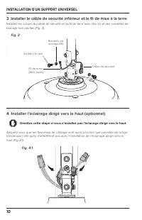
Ground Wire(Green/Yellow) Safety Cable M4 x 10 mm Screw M4 Lock Washer 10 UNIVERSAL MOUNT INSTALLATION 3. Install lower safety cable and ground wire Install safety cable and ground wire lugs with unpainted screws and lock washers (Fig. 3) . 4. Install uplight (optional) Skip this step if you are not...
Page 14 - Connect wiring harnesses
12 UNIVERSAL MOUNT INSTALLATION 5. Connect wiring harnesses No Uplight If not installing an uplight, connect downrod wiring harness to motor unit wiring harness (Fig. 5a) . Uplight Tighten the two set screws at top of uplight. Connect uplight wiring harness to motor unit wiring harness. Connect down...
Page 15 - Position wiring cover and canopy
13 UNIVERSAL MOUNT INSTALLATION 6. Reduce slack Make sure all hardware is secure, and then gently tug cables at top of downrod to reduce slack (Fig. 6) . Make sure rubber plug at top of downrod stays in place. 7. Position wiring cover and canopy Slide wiring cover down the downrod, resting it on the...
Page 16 - Install mounting ball; Do not over-tighten the mounting ball screw.
14 UNIVERSAL MOUNT INSTALLATION 8. Install mounting ball Do not over-tighten the mounting ball screw. Slide mounting ball over downrod (Fig. 8.1) . Insert 6 mm steel pin into hole at top of downrod, and then slide the mounting ball upward, seating the steel pin in the inner slots (Fig. 8.2) . Insert...
Page 17 - Install mounting bracket; WARNING
15 UNIVERSAL MOUNT INSTALLATION 9. Install mounting bracket WARNING Disconnect power to fan location before installing mounting bracket.Mount only to an outlet box marked acceptable for fan support. Secure mounting bracket to mounting structure with suitable hardware (not supplied) (Fig. 9). Outlet ...
Page 18 - Supply Power Wire Colors
16 UNIVERSAL MOUNT INSTALLATION 11. Wire fan WARNING Disconnect power to fan location before wiring fan.Do not connect fan to a damaged power source. Do not attempt to resolve electrical failures on your own. Consult a qualifi ed electrician if uncertain of the electrical installation of this fan. W...
Page 22 - Secure safety cable; Anchor Hook
20 UNIVERSAL MOUNT INSTALLATION 13. Secure safety cable Some local safety codes require the safety cable to be secured directly to an existing part of the building structure (Canada, Singapore). It may be necessary to install additional structural material to provide attachment points. Check your lo...
Page 23 - Building Structure
21 UNIVERSAL MOUNT INSTALLATION Building Structure Loop safety cable around building structure and secure with shackle ( Fig. 13c ). Acceptable building structures include a wooden beam or a metal mounting brace secured between two beams. In some cases, it may be necessary to install additional stru...
Page 25 - Do not expose the remote control to rain or water.; Automate your comfort with SenseME
23 UNIVERSAL MOUNT INSTALLATION 16. Test fan CAUTION Do not expose the remote control to rain or water. Congratulations! Installation is now complete. Turn on power, and then press any button on the remote control to pair it with your fan. Test your fan using the remote ( Fig. 16 ). Note: It is norm...
Page 26 - LOW PROFILE MOUNT INSTALLATION; For Universal Mount installation, see page 6.
24 LOW PROFILE MOUNT INSTALLATION For Universal Mount installation, see page 6. Use the two downtube screw caps that match the color of your fan. The lower cover is shipped attached to the motor unit to protect the fan’s internal electronics during installation. Mounting Plate Wiring and Safety Cabl...
Page 27 - Airfoil Hardware–Step 1; Safety Cable Shackle–Step 6
25 LOW PROFILE MOUNT INSTALLATION Hardware included Airfoil Hardware–Step 1 Mounting Hardware–Step 4, Step 8 Wiring Cover Screws and Downtube Screw Caps–Step 9 x6 x6 Grommet x4 x3 x8 Safety Cable Shackle–Step 6 x1 6 mm Nylock Nut 5/16 " Screw* *One spare screw is included.**Use the two screw cap...
Page 28 - Install rubber bumpers
26 LOW PROFILE MOUNT INSTALLATION 1. Install airfoils Make sure the sticker color on each airfoil matches the corresponding sticker color on the motor unit. Moving clockwise, slide each airfoil edge under the lower cover, align the mounting holes with the holes on the motor unit, and secure with the...
Page 29 - Install mounting plate; Install single mounting bracket
27 LOW PROFILE MOUNT INSTALLATION 3. Install mounting plate WARNING Disconnect power to fan location before installing mounting plate.Mount only to an outlet box marked acceptable for fan support. Secure mounting plate to mounting structure with suitable hardware (not supplied) ( Fig. 3 ). Outlet bo...
Page 30 - Secure safety cable
28 LOW PROFILE MOUNT INSTALLATION 5. Hang fan Raise fan to mounting plate and temporarily rest one rubber bumper in the space between the mounting bracket and mounting plate ( Fig. 5 ). Fig. 5 6. Secure safety cable Two people are recommended for this step, or the fan should be placed upright on a s...
Page 32 - Wire Connector Operation
30 LOW PROFILE MOUNT INSTALLATION Building Structure While supporting the fan, loop safety cable around building structure and secure with shackle ( Fig. 6c ). Acceptable building structures include a wooden beam or a metal mounting brace secured between two beams. In some cases, it may be necessary...
Page 34 - Secure mounting brackets
32 LOW PROFILE MOUNT INSTALLATION 8. Secure mounting brackets Raise fan to mounting plate. Insert one rubber bumper between the mounting plate and the loosely installed mounting bracket. Secure the other bumper with the remaining mounting bracket and 6 mm nylock nuts ( Fig. 8 ). Tighten all four nut...
Page 37 - TROUBLESHOOTING
35 TROUBLESHOOTING Issue Solution The fan jerks upon startup. This is normal and may happen occasionally upon startup. An initial slight jerking forward and backward does not aff ect fan operation. The fan will not start. • Make sure the fan is receiving power. Check your circuit breaker or fuse pan...
Page 39 - MAINTENANCE; Check the safety cable, hardware, and wiring
37 MAINTENANCE WARNING Risk of fire, electric shock, or injury to persons during cleaning and user maintenance. Disconnect the appliance from the power supply before servicing. Please take a few moments each year to perform the following preventative maintenance procedures on your fan to ensure its ...
Page 40 - CONTACT US
38 CONTACT US United States 2348 Innovation DriveLexington, KY 40511USA877-244-3267Outside the U.S. (+1 859-233-1271)bigassfans.com Australia 35 French StreetEagle Farm, BrisbaneQLD 4009Australia+61 1300 244 277bigassfans.com/au Manufacturer 2348 Innovation DriveLexington, KY 40511USA Manufacturing ...
Page 41 - FR A NÇ A IS
Page 42 - CONTENU; Lisez et conservez ces instructions
Rév. A07/13/2022 CONTENU Techniques ...................................................................................................... 1 Avant de commencer .................................................................................. 2 Installation d'un support universel ......................
Page 43 - TECHNIQUES; Support universel
1 TECHNIQUES Support universel Modèles MK-HK4-042406, MK-HK4-041806, MK-HK4-042506,MK-HK4-052406, MK-HK4-051806, MK-HK4-052506,MK-HK4-071806, MK-HK4-071906 Montage Plafonds inclinés ou plats de 2,7 à ≥4,3 m (9 à ≥14 pi) Tension d'entrée 100–240 V CA, 1 Φ, 50–60 Hz Poids maximum 11,8 kg (26 lb) Suppo...
Page 44 - AVANT DE COMMENCER; Préparez le site du ventilateur et rassemblez le matériel; ATTENTION; N'utilisez pas le ventilateur avec un gradateur.; Poutrelle de plafond en bois :; Réunir les outils
2 AVANT DE COMMENCER ☑ Coupez l'alimentation au niveau du disjoncteur Contactez un électricien certifié si vous n'êtes pas à l'aise pour réaliser le travail électrique. Si le code local l'exige, un électricien certifié doit réaliser l'installation du ventilateur. ☑ Préparez le site du ventilateur et...
Page 45 - Vérifiez la pente du plafond (fixation universelle)
3 AVANT DE COMMENCER ☑ Vérifiez la pente du plafond (fixation universelle) Consultez le tableau ci-dessous pour vous assurer que la longueur de la tige d’extension convient à la pente de votre plafond. Les ventilateurs Universal Mount peuvent être installés sur des plafonds plats ou inclinés avec un...
Page 46 - Préparez un plafond en béton (le cas échéant)
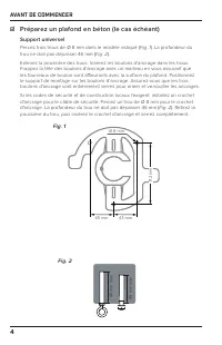
4 AVANT DE COMMENCER ☑ Préparez un plafond en béton (le cas échéant) Support universel Percez trois trous de Ø 8 mm dans le modèle indiqué ( Fig. 1 ). La profondeur du trou ne doit pas dépasser 46 mm ( Fig. 2 ). Enlevez la poussière des trous. Insérez les boulons d'ancrage dans les trous. Frappez la...
Page 47 - Support à profi l bas
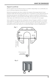
5 40 mm Ø 8 mm (boulon d'ancrage) Ø 8 mm (crochet d’ancrage) 80 mm 100 mm AVANT DE COMMENCER Support à profi l bas Percez quatre trous de Ø 8 mm dans le modèle indiqué ( Fig. 1 ). La profondeur du trou ne doit pas dépasser 46 mm ( Fig. 2 ). Enlevez la poussière des trous. Insérez les boulons d'ancra...
Page 48 - INSTALLATION D'UN SUPPORT UNIVERSEL
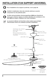
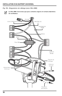
6 INSTALLATION D'UN SUPPORT UNIVERSEL Pour l'installation d'un support à profil bas, voir la page 24. Installez le stabilisateur dans des endroits extérieurs couverts uniquement sur des plafonds plats. Un filtre anti-perturbation électromagnétique (EMI) (non illustré) est inclus pour certaines régio...
Page 49 - Matériel incluse; Matériel de pale – Étape 1
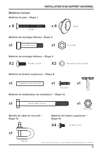
7 INSTALLATION D'UN SUPPORT UNIVERSEL Matériel incluse Matériel de pale – Étape 1 Matériel de montage inférieur - Étape 2 Matériel de montage inférieur – Étape 3 Matériel de fixation supérieure – Étape 8 Matériel de fixation supérieure – Étape 14 Matériel de stabilisateur de ventilateur* – Étape 12 ...
Page 51 - Installer la tige d’extension; Pas d'éclairage dirigé vers le haut; du même côté; sur le côté opposé; Éclairage dirigé vers le haut; côté opposé
9 INSTALLATION D'UN SUPPORT UNIVERSEL 2. Installer la tige d’extension Pas d'éclairage dirigé vers le haut Si vous n'installez pas l'éclairage dirigé vers le haut, alignez les trous de la tige d’extension avec les trous du support du moteur. Positionnez le faisceau de câblage de la tige d’extension ...
Page 54 - Connectez les faisceaux de câblage
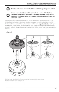
12 INSTALLATION D'UN SUPPORT UNIVERSEL 5. Connectez les faisceaux de câblage Pas d'éclairage dirigé vers le haut Si vous n'installez pas d'éclairage dirigé vers le haut, connectez le faisceau de câbles de la tige d’extension au faisceau de câbles de l'unité moteur (Fig. 5a) . Éclairage dirigé vers l...
Page 56 - Installer la rotule de montage; Ne serrez pas trop la vis à rotule de montage.
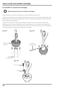
14 INSTALLATION D'UN SUPPORT UNIVERSEL 8. Installer la rotule de montage Ne serrez pas trop la vis à rotule de montage. Faites glisser la rotule de montage sur la tige d’extension (Fig. 8.1) . Insérez une goupille en acier de 6 mm dans le trou en haut de la tige d’extension, puis faites glisser la r...
Page 57 - Installer le support de montage; AVERTISSEMENT; Suspendre le ventilateur
15 INSTALLATION D'UN SUPPORT UNIVERSEL 9. Installer le support de montage AVERTISSEMENT Débranchez l'alimentation au niveau de l'emplacement du ventilateur avant de procéder à l'installation du support de montage.Montez uniquement sur une boîte de sortie marquée acceptable pour le support du ventila...
Page 58 - Ventilateur fi laire; Couleurs des fi ls d'alimentation
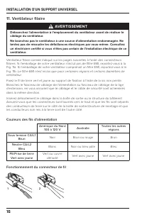
16 INSTALLATION D'UN SUPPORT UNIVERSEL 11. Ventilateur fi laire AVERTISSEMENT Débranchez l'alimentation à l'emplacement du ventilateur avant de réaliser le câblage du ventilateur.Ne branchez pas le ventilateur à une source d'alimentation endommagée. Ne tentez pas de résoudre les défaillances électri...
Page 62 - Sécuriser le câble de sécurité
20 INSTALLATION D'UN SUPPORT UNIVERSEL 13. Sécuriser le câble de sécurité Certains codes de sécurité régionaux exigent que le câble de sécurité soit fi xé directement à une pièce existante de la structure du bâtiment (Canada, Singapour). Il pourrait être nécessaire d'installer un matériau de structu...
Page 63 - Structure de bâtiment; Soulever le couvercle
21 INSTALLATION D'UN SUPPORT UNIVERSEL Structure de bâtiment Enroulez le câble de sécurité autour de la structure du bâtiment et fi xez-le avec une manille ( Fig. 13c ). Les structures de construction acceptables comprennent une poutre en bois ou une entretoise de montage métallique fi xée entre deu...
Page 65 - Testez le ventilateur; Automatisez votre confort avec SenseME
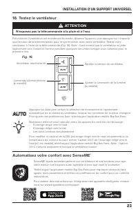
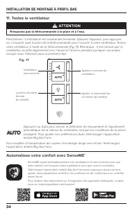
23 INSTALLATION D'UN SUPPORT UNIVERSEL 16. Testez le ventilateur ATTENTION N'exposez pas la télécommande à la pluie et à l'eau. Félicitations! L'installation est maintenant terminée. Allumez l'appareil, puis appuyez sur n'importe quel bouton de la télécommande pour le synchroniser avec votre ventila...
Page 66 - INSTALLATION DE MONTAGE À PROFIL BAS
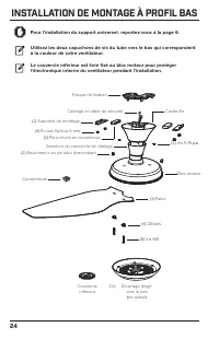
24 INSTALLATION DE MONTAGE À PROFIL BAS Pour l'installation du support universel, reportez-vous à la page 6. Utilisez les deux capuchons de vis du tube vers le bas qui correspondent à la couleur de votre ventilateur. Le couvercle inférieur est livré fixé au bloc moteur pour protéger l'électronique i...
Page 67 - Manille de câble de sécurité – étape 6
25 INSTALLATION DE MONTAGE À PROFIL BAS Matériel incluse Matériel de pale – Étape 1 Matériel de fixation – Étape 4, Étape 8 Vis du couvercle de câblage et capuchons de vis du tube diagonal – Étape 9 x 6 x 6 Œillet X4 x3 x 8 Manille de câble de sécurité – étape 6 x1 Écrou Nylock 6 mm Vis 5/16 po * *U...
Page 68 - Installer des pare-chocs en caoutchouc
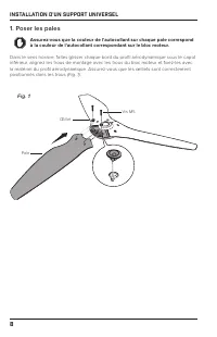
26 INSTALLATION DE MONTAGE À PROFIL BAS 1. Poser les pales Assurez-vous que la couleur de l'autocollant sur chaque pale correspond à la couleur de l'autocollant correspondant sur le bloc moteur. Dans le sens horaire, faites glisser chaque bord du profi l aérodynamique sous le capot inférieur, aligne...
Page 69 - Installer la plaque de fi xation; Installer un support de fi xation unique
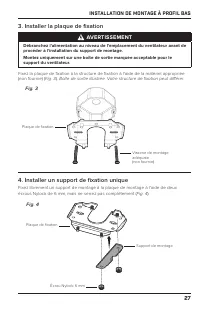
27 INSTALLATION DE MONTAGE À PROFIL BAS 3. Installer la plaque de fi xation AVERTISSEMENT Débranchez l'alimentation au niveau de l'emplacement du ventilateur avant de procéder à l'installation du support de montage.Montez uniquement sur une boîte de sortie marquée acceptable pour le support du venti...
Page 70 - Suspendez le ventilateur
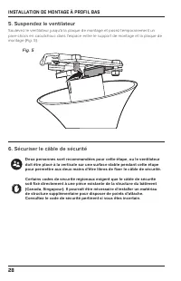
28 INSTALLATION DE MONTAGE À PROFIL BAS 5. Suspendez le ventilateur Soulevez le ventilateur jusqu'à la plaque de montage et posez temporairement un pare-chocs en caoutchouc dans l'espace entre le support de montage et la plaque de montage ( Fig. 5 ). Fig. 5 6. Sécuriser le câble de sécurité Deux per...
Page 72 - Raccorder le ventilateur; Fonctionnement du connecteur de fi l
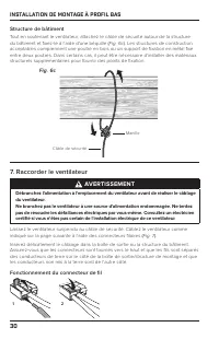
30 INSTALLATION DE MONTAGE À PROFIL BAS Structure de bâtiment Tout en soutenant le ventilateur, attachez le câble de sécurité autour de la structure du bâtiment et fi xez-le à l'aide d'une béquille ( Fig. 6c ). Les structures de construction acceptables comprennent une poutre en bois ou un support d...
Page 73 - Couleurs des fils d'alimentation
31 INSTALLATION DE MONTAGE À PROFIL BAS Fig. 7 SOUS TENSION CA/L1 ROUGE NEUTRE CA/L2 PE/PRISE DE TERRE BRUN BLEU VERT ET JAUNE Couleurs des fils d'alimentation Amérique du Nord 100 à 120 V Australie Toutes les autres régions Sous tension CA/L1 Brun Noir Brun ou rouge Brun Neutre CA/L2 Bleu Blanc Noi...
Page 74 - Supports de montage sécurisés
32 INSTALLATION DE MONTAGE À PROFIL BAS 8. Supports de montage sécurisés Soulevez le ventilateur jusqu'à la plaque de montage. Insérez un pare-chocs en caoutchouc entre la plaque de montage et le support de fi xation desserré. Fixez l'autre pare-chocs avec le support de fi xation restant et les écro...
Page 76 - Testez le ventilateur
34 INSTALLATION DE MONTAGE À PROFIL BAS 11. Testez le ventilateur ATTENTION N'exposez pas la télécommande à la pluie et à l'eau. Félicitations ! L'installation est maintenant terminée. Allumez l'appareil, puis appuyez sur n'importe quel bouton de la télécommande pour l'assortir à votre ventilateur. ...
Page 77 - DÉPANNAGE
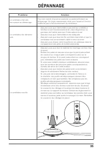
35 DÉPANNAGE Problème Solution Le ventilateur fait des secousses au démarrage. Ceci est normal et peut se produire occasionnellement au démarrage. Un léger mouvement initial vers l'avant et l'arrière n'aff ecte pas le fonctionnement du ventilateur. Le ventilateur de démarre pas. • Assurez-vous que l...
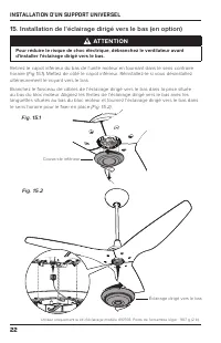
Page 79 - ENTRETIEN; Vérifiez le câble de sécurité, le matériel et le câblage; Éclairage dirigé vers le bas :; Éclairage dirigé vers le haut :
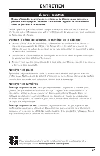
37 ENTRETIEN AVERTISSEMENT Risque d'incendie, de décharge électrique ou de blessures aux personnes pendant le nettoyage et l'entretien. Débranchez l'appareil de l'alimentation avant de procéder à un entretien. Veuillez prendre quelques instants chaque année pour effectuer les procédures d'entretien ...
Page 80 - NOUS JOINDRE
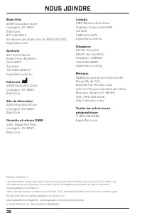
38 NOUS JOINDRE États-Unis 2348 Innovation DriveLexington, KY 40511États-Unis877-244-3267En dehors des États-Unis (+1 859-233-1271)bigassfans.com Australie 35 French StreetEagle Farm, BrisbaneQLD 4009Australie+61 1300 244 277bigassfans.com/au Fabricant 2348 Innovation DriveLexington, KY 40511États-U...
Page 81 - ESPA ÑOL
Page 82 - CONTENIDO; Lea y guarde estas instrucciones
Rev. A07/13/2022 CONTENIDO Especificaciones ............................................................................................ 1 Antes de comenzar ...................................................................................... 2 Instalación del montaje universal .......................
Page 83 - ESPECIFICACIONES; Montaje universal
1 ESPECIFICACIONES Montaje universal Modelos MK-HK4-042406, MK-HK4-041806, MK-HK4-042506,MK-HK4-052406, MK-HK4-051806, MK-HK4-052506,MK-HK4-071806, MK-HK4-071906 Montaje Techos inclinados o planos de 9 a ≥14 ft (2.7 a ≥4.3 m) Voltaje de entrada 100–240 VCA, 1 Φ, 50–60 Hz Peso máximo 26 lb (11.8 kg) ...
Page 84 - ANTES DE COMENZAR; PRECAUCIÓN; No utilice el ventilador con un interruptor de atenuación.; Viga de techo de madera:; Reúna las herramientas
2 ANTES DE COMENZAR ☑ Desconecte el suministro eléctrico desde el disyuntor Si no se siente seguro realizando trabajos eléctricos, recurra a un electricista. Si el código local lo exige, el ventilador debe ser instalado por un electricista certificado. ☑ Prepare el lugar de instalación del ventilado...
Page 85 - Verifique la pendiente del techo (montaje universal)
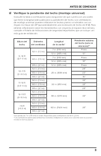
3 ANTES DE COMENZAR ☑ Verifique la pendiente del techo (montaje universal) Consulte la tabla a continuación para asegurarse de que cuenta con una varilla que tiene la longitud adecuada para su pendiente del techo. Los ventiladores de montaje universal pueden instalarse en techos planos o inclinados ...
Page 86 - Preparación del techo de concreto (si corresponde)
4 ANTES DE COMENZAR ☑ Preparación del techo de concreto (si corresponde) Montaje universal Perfore tres orifi cios de Ø 8 mm en el patrón que se muestra ( Fig. 1 ). La profundidad del orifi cio no debe exceder los 46 mm ( Fig. 2 ). Elimine el polvo de los orifi cios. Inserte los pernos de anclaje en...
Page 87 - Montaje de bajo perfi l
5 40 mm Ø 8 mm (perno de anclaje) Ø 8 mm (gancho de anclaje) 80 mm 100 mm ANTES DE COMENZAR Montaje de bajo perfi l Perfore cuatro orifi cios de Ø 8 mm en el patrón que se muestra ( Fig. 1 ). La profundidad del orifi cio no debe exceder los 46 mm ( Fig. 2 ). Elimine el polvo de los orifi cios. Inser...
Page 88 - INSTALACIÓN DEL MONTAJE UNIVERSAL
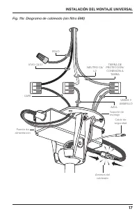
6 INSTALACIÓN DEL MONTAJE UNIVERSAL Para la instalación del montaje de bajo perfil, consulte la página 24. Instale el estabilizador del ventilador en exteriores cubiertos en techos planos únicamente. Se incluye un filtro EMI (no se muestra) para ciertas regiones y diámetros de ventilador. Si el filt...
Page 89 - Accesorios incluidos; Accesorios para las aspas aerodinámicas: paso 1
7 INSTALACIÓN DEL MONTAJE UNIVERSAL Accesorios incluidos Accesorios para las aspas aerodinámicas: paso 1 Accesorios para el montaje inferior: paso 2 Accesorios para el montaje inferior: paso 3 Accesorios para el montaje superior: paso 8 Accesorios para el montaje superior: paso 14 Accesorios para el...
Page 90 - Instale las aspas aerodinámicas
8 INSTALACIÓN DEL MONTAJE UNIVERSAL 1. Instale las aspas aerodinámicas Asegúrese de que el color de la etiqueta de cada aspa aerodinámica coincida con el color de la etiqueta correspondiente en la unidad del motor. Desplazándose en el sentido de las manecillas del reloj, deslice cada borde del aspa ...
Page 91 - Instale la varilla; Sin luz ascendente; mismo lado; lado; Luz ascendente; lado opuesto
9 INSTALACIÓN DEL MONTAJE UNIVERSAL 2. Instale la varilla Sin luz ascendente Si no va a instalar una luz ascendente, alinee los orifi cios de la varilla con los orifi cios del soporte del motor. Coloque el arnés del cableado de la varilla, de modo que esté en el mismo lado del eje del motor que el a...
Page 92 - Instale el cable de seguridad inferior y el cable de tierra; No realice este paso si no va a instalar la luz ascendente.
Cable de tierra(verde/amarillo) Cable de seguridad Tornillo M4 x 10 mm Arandela de seguridad M4 10 INSTALACIÓN DEL MONTAJE UNIVERSAL 3. Instale el cable de seguridad inferior y el cable de tierra Instale las terminales del cable de seguridad y del cable de tierra con los tornillos sin pintar y las a...
Page 94 - Conecte los arneses del cableado
12 INSTALACIÓN DEL MONTAJE UNIVERSAL 5. Conecte los arneses del cableado Sin luz ascendente Si no va a instalar una luz ascendente, conecte el arnés de cableado de la varilla al arnés de cableado de la unidad del motor (Fig. 5a) . Luz ascendente Fije los dos tornillos de la parte superior de la luz ...
Page 95 - Reduzca la holgura
13 INSTALACIÓN DEL MONTAJE UNIVERSAL 6. Reduzca la holgura Cerciórese de que todos los accesorios estén asegurados y, luego, tire suavemente de los cables en la parte superior de la varilla para reducir la holgura ( Fig. 6 ). Asegúrese de que el tapón de goma en la parte superior de la varilla se ma...
Page 96 - Instale la bola de montaje; No apriete demasiado el tornillo de la bola de montaje.
14 INSTALACIÓN DEL MONTAJE UNIVERSAL 8. Instale la bola de montaje No apriete demasiado el tornillo de la bola de montaje. Deslice la bola de montaje por la varilla ( Fig. 8.1 ). Inserte el pasador de acero de 6 mm en el orifi cio que se encuentra en la parte superior de la varilla y, luego, deslice...
Page 97 - Instale el soporte de montaje; ADVERTENCIA; Cuelgue el ventilador
15 INSTALACIÓN DEL MONTAJE UNIVERSAL 9. Instale el soporte de montaje ADVERTENCIA Antes de instalar el soporte de montaje, desconecte la corriente del lugar donde se colocará el ventilador.Monte solo en una caja de distribución marcada como aceptable para soportar el ventilador. Fije el soporte de m...
Page 98 - Conecte el ventilador; Colores de los cables de la fuente alimentación
16 INSTALACIÓN DEL MONTAJE UNIVERSAL 11. Conecte el ventilador ADVERTENCIA Antes de cablear el ventilador, desconecte la corriente del lugar donde se hará la instalación.No conecte el ventilador a una fuente de alimentación dañada. No intente reparar fallas eléctricas por su cuenta. Si tiene alguna ...
Page 101 - Instale el estabilizador del ventilador (si está incluido)
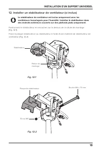
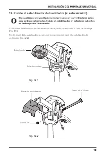
19 INSTALACIÓN DEL MONTAJE UNIVERSAL 12. Instale el estabilizador del ventilador (si está incluido) El estabilizador del ventilador se incluye solo con los ventiladores aptos para ambientes húmedos. Instale el estabilizador en exteriores cubiertos en techos planos únicamente. Coloque el estabilizado...
Page 102 - Fije el cable de seguridad; Gancho de anclaje
20 INSTALACIÓN DEL MONTAJE UNIVERSAL 13. Fije el cable de seguridad Algunos códigos de seguridad locales exigen que el cable de seguridad se fi je directamente a una parte existente de la estructura del edifi cio (Canadá, Singapur). Es posible que sea necesario instalar materiales estructurales adic...
Page 103 - Estructura del edifi cio
21 INSTALACIÓN DEL MONTAJE UNIVERSAL Estructura del edifi cio Haga pasar el cable de seguridad alrededor de la estructura del edifi cio y fíjelo con el grillete ( Fig. 13c ). Las estructuras aceptables incluyen una viga de madera o una abrazadera de montaje de metal fi jada entre las dos vigas. En a...
Page 105 - Pruebe el ventilador; No exponga el control remoto a la lluvia ni al agua.; Automatice su comodidad con SenseME
23 INSTALACIÓN DEL MONTAJE UNIVERSAL 16. Pruebe el ventilador PRECAUCIÓN No exponga el control remoto a la lluvia ni al agua. ¡Felicitaciones! La instalación ya está completa. Encienda la alimentación y, luego, presione cualquier botón del control remoto para emparejarlo con su ventilador. Pruebe su...
Page 106 - INSTALACIÓN DEL MONTAJE DE BAJO PERFIL; Para la instalación del montaje universal, consulte la página 6.
24 INSTALACIÓN DEL MONTAJE DE BAJO PERFIL Para la instalación del montaje universal, consulte la página 6. Use las dos tapas roscadas del tubo descendente que coincidan con el color de su ventilador. La cubierta inferior se envía junto con la unidad del motor para proteger los componentes electrónic...
Page 107 - Grillete del cable de seguridad: paso 6
25 INSTALACIÓN DEL MONTAJE DE BAJO PERFIL Accesorios incluidos Accesorios para las aspas aerodinámicas: paso 1 Accesorios para el montaje: paso 4, paso 8 Tornillos de la cubierta del cableado y tapas roscadas del tubo descendente: paso 9 x6 x6 Ojal x4 x3 x8 Grillete del cable de seguridad: paso 6 x1...
Page 108 - Instale los amortiguadores de goma
26 INSTALACIÓN DEL MONTAJE DE BAJO PERFIL 1. Instale las aspas aerodinámicas Asegúrese de que el color de la etiqueta de cada aspa aerodinámica coincida con el color de la etiqueta correspondiente en la unidad del motor. Desplazándose en el sentido de las manecillas del reloj, deslice cada borde del...
Page 109 - Instale la placa de montaje; Instale un soporte de montaje único
27 INSTALACIÓN DEL MONTAJE DE BAJO PERFIL 3. Instale la placa de montaje ADVERTENCIA Antes de instalar la placa de montaje, desconecte la energía eléctrica del lugar donde se colocará el ventilador.Monte solo en una caja de distribución marcada como aceptable para soportar el ventilador. Fije la pla...
Page 110 - Cuelgue el ventilador
28 INSTALACIÓN DEL MONTAJE DE BAJO PERFIL 5. Cuelgue el ventilador Levante el ventilador hasta la placa de montaje y apoye temporalmente un amortiguador de goma en el espacio entre el soporte de montaje y la placa de montaje ( Fig. 5 ). Fig. 5 6. Fijación del cable de seguridad Se recomienda que dos...
Page 112 - Conecte el ventilador; Funcionamiento de los conectores de cables
30 INSTALACIÓN DEL MONTAJE DE BAJO PERFIL Estructura del edifi cio Mientras sostiene el ventilador, haga pasar el cable de seguridad alrededor de la estructura del edifi cio y fíjelo con el grillete ( Fig. 6c ). Las estructuras aceptables incluyen una viga de madera o una abrazadera de montaje de me...
Page 114 - Fije los soportes de montaje
32 INSTALACIÓN DEL MONTAJE DE BAJO PERFIL 8. Fije los soportes de montaje Levante el ventilador hasta la placa de montaje. Inserte un amortiguador de goma entre la placa de montaje y el soporte de montaje instalado sin ajustar. Fije el otro amortiguador con el soporte de montaje restante y las tuerc...
Page 116 - Pruebe el ventilador
34 INSTALACIÓN DEL MONTAJE DE BAJO PERFIL 11. Pruebe el ventilador PRECAUCIÓN No exponga el control remoto a la lluvia ni al agua. ¡Felicitaciones! La instalación ya está completa. Encienda la alimentación y, luego, presione cualquier botón del control remoto para emparejarlo con su ventilador. Prue...
Page 117 - RESOLUCIÓN DE PROBLEMAS
35 RESOLUCIÓN DE PROBLEMAS Problema Solución El ventilador se sacude al arrancar. Esto es normal y puede ocurrir de vez en cuando al ponerlo en marcha. Una ligera sacudida inicial hacia delante y hacia atrás no afecta al funcionamiento del ventilador. El ventilador no enciende. • Asegúrese de que el...
Page 119 - MANTENIMIENTO; Verifique el cable de seguridad, los accesorios y el cableado
37 MANTENIMIENTO ADVERTENCIA Riesgo de incendio, descarga eléctrica o lesión personal al limpiar o dar mantenimiento al aparato. Desconéctelo de la fuente de alimentación antes de realizar el mantenimiento. Realice los siguiente procedimientos de mantenimiento preventivo de forma anual para garantiz...
Page 120 - CONTÁCTENOS
38 CONTÁCTENOS Estados Unidos 2348 Innovation DriveLexington, KY 40511Estados Unidos877-244-3267Fuera de Estados Unidos (+1 859-233-1271)bigassfans.com Australia 35 French StreetEagle Farm, BrisbaneQLD 4009Australia+61 1300 244 277bigassfans.com/au Fabricante 2348 Innovation DriveLexington, KY 40511...