Page 3 - IT; CONSIGLI E SUGGERIMENTI; INSTALLAZIONE; • Il fabbricante non potrà ritenersi responsabile per eventuali
IT 3 3 CONSIGLI E SUGGERIMENTI Le Istruzioni per l’uso si riferiscono ai diversi modelli di questo apparecchio. Pertanto, si potrebbero trovare descrizioni di singole caratteristiche che non appartengono al proprio apparecchio specifico. INSTALLAZIONE • Il fabbricante non potrà ritenersi responsabil...
Page 4 - USO
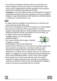
IT 4 4 • Se le istruzioni di installazione del piano cottura a gas specificano una distanza maggiore di quella sopra indicata, è necessario tenerne conto. Devono essere rispettate tutte le normative riguardanti lo scarico dell'aria. • Usare solo viti e minuteria di tipo idoneo per la cappa. Avverten...
Page 5 - : le parti accessibili possono diventare molto calde durante; MANUTENZIONE; qualunque operazione di pulizia o manutenzione.
IT 5 5 • “ ATTENZIONE : le parti accessibili possono diventare molto calde durante l’uso degli apparecchi di cottura ”. MANUTENZIONE • Spegnere o scollegare l’apparecchio dalla rete di alimentazione prima di qualunque operazione di pulizia o manutenzione. • Pulire e/o sostituire i filtri dopo il per...
Page 6 - CARATTERISTICHE; Componenti
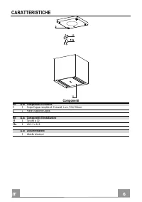
IT 6 6 CARATTERISTICHE Componenti Rif. Q.tà Componenti di Prodotto 1 1 Corpo Cappa completo di: Comandi, Luce, Filtri, Motore. 2 1 Piastra supporto Cappa. Rif. Q.tà Componenti di Installazione 11 4 Tasselli ø 10 12a 4 Viti 4,2 x 44,4 Q.tà Documentazione 1 Libretto Istruzioni
Page 7 - Ingombro
Page 8 - Sequenza operazioni Installazione; ve restare frontalmente l’installatore.
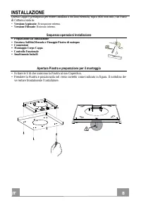
IT 8 8 INSTALLAZIONE Questa Cappa è predisposta per essere installata a Soffitto/Mensola, sopra (650 mm min.) un Piano di Cottura a isola in: • Versione Aspirante : Evacuazione esterna. • Versione Filtrante : Ricircolo interno. Sequenza operazioni Installazione • Preparazione all’Installazione • For...
Page 9 - Foratura Soffitto/Mensola e Fissaggio Piastra; FORATURA SOFFITTO/MENSOLA; come indicato in figura.
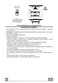
IT 9 9 Foratura Soffitto/Mensola e Fissaggio Piastra FORATURA SOFFITTO/MENSOLA • Con l’ausilio di un Filo a piombo riportare sul Soffitto/Mensola di supporto il centro del Piano Cottura. • Appoggiare al Soffitto/Mensola la Piastra facendo attenzione a posizionarla nel verso giusto, come indicato in ...
Page 10 - FISSAGGIO PIASTRA
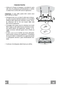
IT 1 10 FISSAGGIO PIASTRA • Sollevare la Piastra di fissaggio e incastrare le asole sulle due viti predisposte precedentemente al soffitto e ruotare fino al centro dell’asola di regolazione. Attenzione : Il verso della piastra deve essere come quello indicato in figura • Stringere le due viti e avvi...
Page 11 - COLLEGAMENTO CAVI CAPPA-PIASTRA
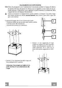
IT 1 11 COLLEGAMENTO CAVI CAPPA-PIASTRA N.B. Prima di proseguire con l’Installazione è necessario portare la Cappa all’altezza di almeno 650 mm dal piano di cottura con un supporto o con l’aiuto di una se-conda persona. Attenzione a non superare la quota massima di estensione della Cappa indicata ne...
Page 12 - • Infilare i pomelli di sicurezza (
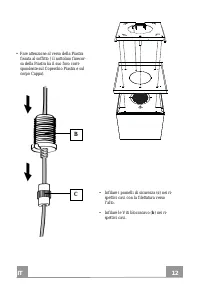
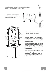
IT 1 12 • Fare attenzione al verso della Piastra fissata al soffitto ( il nottolino finecor-sa della Piastra ha il suo foro corri-spondente sul Coperchio Piastra e sul corpo Cappa). • Infilare i pomelli di sicurezza ( c ) nei ri- spettivi cavi con la filettatura verso l’alto. • Infilare le Viti bloc...
Page 13 - • Passare i Cavi nelle asole dei Nottolini filettati (
IT 1 13 • Passare i Cavi nelle asole dei Nottolini filettati ( a ) ed avvi- tare le Viti bloccacavo ( b ) ai Nottolini stessi. • Ad operazione terminata il risul- tato deve essere come indicato in figura per tutti e 4 i Cavi. • Arrivati a questo punto abbiamo tutti e 4 i Cavi collegati alla Piastra....
Page 14 - LIVELLAMENTO DELLA CAPPA
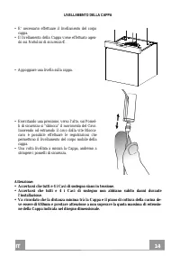
IT 1 14 LIVELLAMENTO DELLA CAPPA • E’ necessario effettuare il livellamento del corpo cappa. • Il livellamento della Cappa viene effettuato agen- do sui Nottolini di sicurezza C . • Appoggiare una livella sulla cappa. • Esercitando una pressione, verso l’alto, sui Pomel- li di sicurezza si “sblocca”...
Page 15 - Connessioni; USCITA ARIA VERSIONE ASPIRANTE
IT 1 15 Connessioni USCITA ARIA VERSIONE ASPIRANTE Per l’installazione della Cappa in versione Aspirante fare riferi-mento alle istruzioni contenute nel Kit aspirante specifico per la Cappa. USCITA ARIA VERSIONE FILTRANTE • Aprire il Gruppo Illuminazione tirandolo sull’apposita intacca. • Togliere i...
Page 16 - FISSAGGIO DEL CAVO ALIMENTAZIONE; • Portare in tensione il Cavo alimentazione e fissar-; MONTAGGIO COPERCHIO PIASTRA; • Riavvitare il Coperchio alla Piastra con le Viti tol-
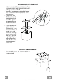
IT 1 16 FISSAGGIO DEL CAVO ALIMENTAZIONE • Portare in tensione il Cavo alimentazione e fissar- lo alla Staffa sulla Piastra a soffitto usando la lin-guetta già montata con 2 Viti. • Incastrare il passacavo in gomma già infilato sul Cavo alimentazione all’asola per evitare futuri danneggiamenti. • Co...
Page 17 - Quadro comandi; cando che la Cappa ha superato il finecorsa........
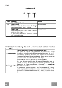
IT 1 17 USO Quadro comandi L T1 Tasto Funzione Display L Accende/Spegne le luci. - T1 Cappa Bassa Premuto per 2 secondi solleva la Cappa. Premuto brevemente On/Off Motore. Acceso/Spento Cappa Alta Prima pressione: La Cappa scende. Seconda pressione: Stop Cappa. A movimento terminato il motore si acc...
Page 18 - TELECOMANDO; • Non disperdere le pile nell’ambiente, depositarle ne-
IT 1 18 TELECOMANDO Questo apparecchio può essere comandato per mezzo di un telecomando, alimentato con pile alcaline zinco-carbone da 1,5 V del tipo standard LR03-AAA (non incluse). • Non riporre il telecomando in prossimità di fonti di calore. • Non disperdere le pile nell’ambiente, depositarle ne...
Page 19 - Filtro antigrasso metallico; PULIZIA FILTRO ANTIGRASSO METALLICO; Filtri antiodore al Carbone attivo (Versione Filtrante); SOSTITUZIONE; Illuminazione
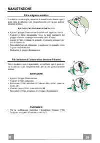
IT 1 19 MANUTENZIONE Filtro antigrasso metallico Lavabile in lavastoviglie, necessita di essere lavato almeno ogni 2 mesi circa di utilizzo o più frequentemente, per un uso partico-larmente intenso. PULIZIA FILTRO ANTIGRASSO METALLICO • Aprire il gruppo illuminazione tirandolo sull’apposita intacca....
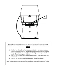
Page 20 - Procedura di intervento in caso di anomalie sul movimento
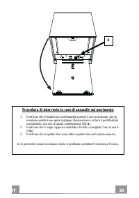
IT 2 20 Procedura di intervento in caso di anomalie sul movimento 1. Verificare che il fusibile sia correttamente inserito e non sia bruciato, per un eventuale sostituzione aprire il gruppo illuminazione e svitare il portafusibile sostituendolo con uno di uguali caratteristiche (Rif. A ). 2. Verific...
Page 21 - DE; EMPFEHLUNGEN UND HINWEISE; INSTALLATION
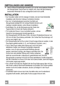
DE 2 21 EMPFEHLUNGEN UND HINWEISE Diese Gebrauchsanleitungen beziehen sich auf die verschiedenen Modelle der Abzugshaube. Darum kann es möglich sein, dass die Beschreibung bestimmter Merkmale für das vorliegende Gerät nicht zutrifft. INSTALLATION • Der Hersteller haftet nicht für etwaige Schäden, di...
Page 22 - von mindestens 3 mm an das Netz anschließen.; GEBRAUCH; • Fritteusen müssen während des Gebrauchs ständig
DE 2 22 • Falls die Montageanweisungen für die gasbetriebene Kochmulde einen größeren Abstand vorschreiben, als der oben angegebene, muss diese Vorgabe befolgt werden. Es sind sämtliche Abluftvorschriften zu beachten. • Nur für die Abzugshaube geeignete Schrauben und Kleinteile verwenden. Achtung : ...
Page 23 - WARTUNG
DE 2 23 • ACHTUNG: Die zugänglichen Teile können während des Gebrauchs der Kochgeräte sehr heiß werden. WARTUNG • Vor Reinigungs- oder Wartungsarbeiten am Gerät, muss dieses ausgeschaltet und spannungslos gemacht werden. • Die Filter stets nach den angegebenen Intervallen reinigen oder auswechseln (...
Page 24 - CHARAKTERISTIKEN; Komponenten
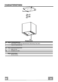
DE 2 24 CHARAKTERISTIKEN Komponenten Bez. Menge Produktkomponenten 1 1 Haubenkörper, komplett mit: Bedienelemente, Beleuchtung, Filter, Motor 2 1 Platte der Haubenhalterung Bez. Menge Installationskomponenten 11 4 Dübel ø 10 mm 12a 4 Schrauben 4,2 x 44,4 Menge Dokumentation 1 Betriebsanleitung
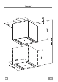
Page 25 - Platzbedarf
Page 26 - MONTAGE; Sequenz der Installationsarbeiten; Öffnen der Platte und Vorbereitung für die Montage; Die Sperrklinke muss frontal zum Installateur verbleiben.
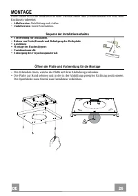
DE 2 26 MONTAGE Diese Haube ist für die Installation an einer Decke/Konsole über (Mindestabstand 650 mm) einer Kochinsel vorbereitet: • Abluftversion : Abluftleitung nach Außen. • Umluftversion : Innere Rezirkulation. Sequenz der Installationsarbeiten • Vorbereitung zur Installation. • Bohren von De...
Page 27 - Bohren von Decke/Konsole und Befestigung der Platte; BOHREN VON DECKE/KONSOLE; mitgelieferten Dübel
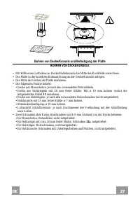
DE 2 27 Bohren von Decke/Konsole und Befestigung der Platte BOHREN VON DECKE/KONSOLE • Mit Hilfe eines Lotfadens an Decke/Haltekonsole die Mitte des Kochfelds anzeichnen. • Die Platte in der korrekten Einbaurichtung an der Decke/Konsole anlegen. • Die Mitte der Löcher der Platte markieren. • Die fol...
Page 28 - BEFESTIGUNG DER PLATTE
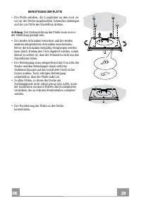
DE 2 28 BEFESTIGUNG DER PLATTE • Die Platte anheben, die Langlöcher an den zwei zu- vor an der Decke angebrachten Schrauben einhängen und bis zur Mitte der Einstellöse drehen. Achtung : Die Einbaurichtung der Platte muss wie in der Abbildung gezeigt sein. • Die beiden Schrauben festziehen und die be...
Page 29 - VERBINDUNG DER SEILE ZWISCHEN HAUBE UND PLATTE; • Sperrklinke mit Gewinde (
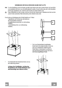
DE 2 29 a b c VERBINDUNG DER SEILE ZWISCHEN HAUBE UND PLATTE NB: Vor der Installation muss die Haube mit Hilfe einer Stütze oder einer zweiten Person auf eine Höhe von mindestens 650 mm vom Kochfeld gebracht werden. Darauf achten, dass die in der bemaßten Zeichnung angegebene max. Extension der Haub...
Page 30 - • Die Sicherheitsknäufe (
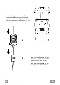
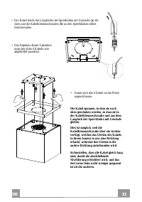
DE 3 30 B C • Auf die Richtung der an der Decke befestigten Platte achten (ein entsprechendes Loch der Sperrklinke des Endanschlags der Platte findet sich an der Abdeckung der Platte und am Hau-benkörper). • Die Sicherheitsknäufe ( c ) mit nach oben zeigendem Gewinde auf die entsprechenden Seile ste...
Page 31 - • Die Kabel durch die Langlöcher der Sperrklinke mit Gewinde (
DE 3 31 • Die Kabel durch die Langlöcher der Sperrklinke mit Gewinde ( a ) ste- cken und die Kabelklemmschrauben ( b ) an den Sperrklinken selbst festschrauben. • Das Ergebnis dieser Operation muss bei allen 4 Kabeln wie abgebildet aussehen. • Damit sind alle 4 Kabel an die Platte angeschlossen. Die...
Page 32 - NIVELLIEREN DER ABZUGSHAUBE; ken auf die Sicherheits-Sperrklinke
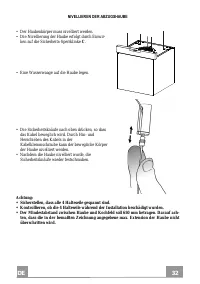
DE 3 32 NIVELLIEREN DER ABZUGSHAUBE • Der Haubenkörper muss nivelliert werden. • Die Nivellierung der Haube erfolgt durch Einwir- ken auf die Sicherheits-Sperrklinke C . • Eine Wasserwaage auf die Haube legen. • Die Sicherheitsknäufe nach oben drücken, so dass das Kabel beweglich wird. Durch Hin- un...
Page 33 - Anschlüsse; LUFTAUSTRITT BEI DER ABLUFTVERSION; • Die Beleuchtungseinheit öffnen, indem sie zur entsprechenden
DE 3 33 Anschlüsse LUFTAUSTRITT BEI DER ABLUFTVERSION Für die Installation der Ablufthaube wird auf die Anleitungen verwiesen, die im spezifischen Abluft-Bausatz für die Haube enthalten ist. LUFTAUSTRITT BEI DER FILTERVERSION • Die Beleuchtungseinheit öffnen, indem sie zur entsprechenden Kerbe gezog...
Page 34 - BEFESTIGUNG DES STROMKABELS
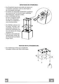
DE 3 34 BEFESTIGUNG DES STROMKABELS • Das Stromkabel spannen und mittels der bereits mit 2 Schrauben montierten Lasche an dem Bügel an der Deckenplatte befestigen. • Die bereits am Stromkabel aufgesteckte Lippklampe aus Gummi an der Öse fixieren, damit zukünftige Beschädigungen vermieden werden. • B...
Page 35 - BEDIENUNG; Schalttafel
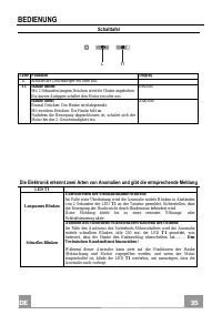
DE 3 35 BEDIENUNG Schalttafel L T1 Taste Funktion Display L Schaltet die Leuchtkörper ein oder aus. - T1 Haube unten: Mit 2 Sekunden langem Drücken wird die Haube angehoben. Ein kurzes Antippen schaltet den Motor ein oder aus. Ein/Aus Haube oben: Einmal Drücken: Die Haube wird abgesenkt. Mit zweitem...
Page 36 - FERNBEDIENUNG; Batterien müssen vorschriftsmäßig entsorgt werden.
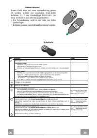
DE 3 36 FERNBEDIENUNG Dieses Gerät kann mit einer Fernbedienung gesteu-ert werden, welche mit alkalischen Zink-Kohle-Batterien 1,5 V des Standardtyps LR03-AAA ver-sorgt wird (nicht im Lieferumfang enthalten). • Die Fernbedienung nicht in die Nähe von Hitze-quellen legen. • Batterien müssen vorschrif...
Page 37 - Metallfettfilter; REINIGUNG DES METALLFETTFILTERS; Beleuchtung
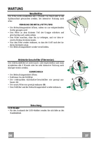
DE 3 37 WARTUNG Metallfettfilter Der Filter sollte mindestens alle 2 Monate von Hand oder in der Spülmaschine gewaschen werden, bei intensiver Nutzung auch öfter. REINIGUNG DES METALLFETTFILTERS • Die Beleuchtungseinheit öffnen, indem sie zur entsprechenden Kerbe gezogen wird • Den Filter zu dem hin...
Page 38 - Prozedur für den Fall von Anomalien der Bewegung; Prüfen, ob alle vier Seile gleichmäßig gespannt sind.
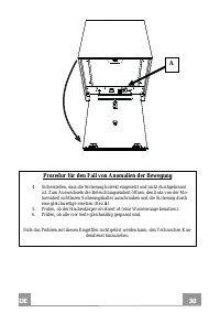
DE 3 38 Prozedur für den Fall von Anomalien der Bewegung 4. Sicherstellen, dass die Sicherung korrekt eingesetzt und nicht durchgebrannt ist. Zum Auswechseln die Beleuchtungseinheit öffnen, den links von der Mo-toreinheit sichtbaren Sicherungshalter ausschrauben und die Sicherung durch eine gleichwe...
Page 39 - EN; RECOMMENDATIONS AND SUGGESTIONS
EN 3 39 RECOMMENDATIONS AND SUGGESTIONS The Instructions for Use apply to several versions of this appliance. Accordingly, you may find descriptions of individual features that do not apply to your specific appliance. INSTALLATION • The manufacturer will not be held liable for any damages resulting ...
Page 40 - USE
EN 4 40 • If the instructions for installation for the gas hob specify a greater distance specified above, this has to be taken into account. Regulations concerning the discharge of air have to be fulfilled. • Use only screws and small parts in support of the hood. Warning : Failure to install the s...
Page 41 - : Accessible parts may become hot when used with cooking; MAINTENANCE; any maintenance work.
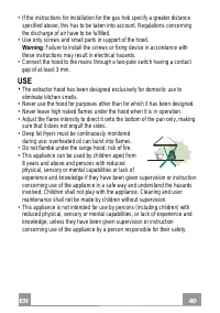
EN 4 41 • “ CAUTION : Accessible parts may become hot when used with cooking appliances.” MAINTENANCE • Switch off or unplug the appliance from the mains supply before carrying out any maintenance work. • Clean and/or replace the Filters after the specified time period (Fire hazard). • The Grease fi...
Page 42 - CHARACTERISTICS
EN 4 42 CHARACTERISTICS Components Ref. Q.ty Product Components 1 1 Hood Canopy complete with: Controls, Light, Filters, Motor. 2 1 Hood support plate. Ref. Q.ty Installation Components 11 4 Wall Plugs ø 10 12a 4 Screws 4.2 x 44.4 Q.ty Documentation 1 Instruction Manual
Page 43 - Dimensions
Page 44 - Sequence of operations - Installation; Opening the Plate and preparing for assembly; face towards the installer.
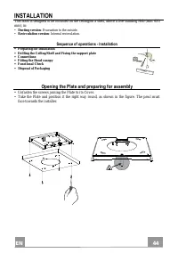
EN 4 44 INSTALLATION This hood is designed to be mounted on the ceiling/on a shelf, above a free-standing Hob (min. 650 mm), in: • Ducting version : Evacuation to the outside. • Recirculation version : Internal recirculation. Sequence of operations - Installation • Preparing for installation • Drill...
Page 45 - Ceiling/Shelf drilling and Plate Fixing; CEILING/SHELF DRILLING; Plugs
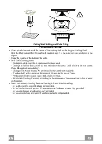
EN 4 45 Ceiling/Shelf drilling and Plate Fixing CEILING/SHELF DRILLING • Use a plumb-line and mark the centre of the cooking hob on the Support Ceiling/Shelf • Rest the Plate against the Ceiling/Shelf, making sure it is the right way up, as shown in the figure. • Mark the centres of the holes in the...
Page 46 - FIXING THE PLATE
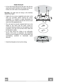
EN 4 46 FIXING THE PLATE • Lift up the Fixing plate and fit the slots onto the two screws previously inserted in the ceiling, and turn un-til they are at the centre of the adjustment slot. Warning : The plate must be facing in the direction shown in the figure • Tighten the two screws completely and...
Page 47 - CONNECTING HOOD-PLATE CABLES; on the ceiling, and this; must be; done without the weight of the Hood bearing down on
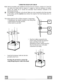
EN 4 47 CONNECTING HOOD-PLATE CABLES N.B. Before proceeding with installation the Hood must be raised to a height of at least 650 mm above the cooker hob by means of a support or with the assistance of another person. Be careful not to exceed the maximum Hood extension indicated in the dimensional d...
Page 48 - • Insert the safety knobs (
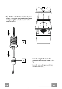
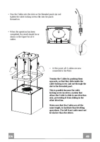
EN 4 48 b c • Pay attention to the direction in which the Plate is fixed to the ceiling (the Plate limit pawl has a corresponding hole on the Plate cover and on the Hood canopy). • Insert the safety knobs ( c ) into the respective cables, with the thread to the top. • Insert the cable locking screws...
Page 49 - • Pass the Cables into the slots on the threaded pawls (
EN 4 49 • Pass the Cables into the slots on the threaded pawls ( a ) and tighten the cable locking screws ( b ) into the pawls themselves. • When the operation has been completed, the result should be as shown in the figure for all 4 cables. • At this point, all 4 cables are now connected to the Pla...
Page 50 - LEVELLING THE HOOD; • Rest a spirit level on the hood.; 50mm and make sure that you; do not exceed the maximum Hood extension
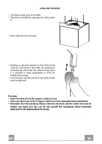
EN 5 50 LEVELLING THE HOOD • The hood canopy must be levelled. • The Hood is levelled by adjusting the safety pawls C . • Rest a spirit level on the hood. • Exerting an upwards pressure on the safety knobs “unlocks” movement of the Cable. By inserting or extracting the cable from the cable locking s...
Page 51 - Connections; AIR OUTLET - DUCTING VERSION
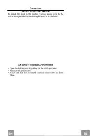
EN 5 51 Connections AIR OUTLET - DUCTING VERSION To install the hood in the ducting version, please refer to the instructions provided in the ducting kit specific to the hood. AIR OUTLET – RECIRCULATION VERSION • Open the lighting unit by pulling on the notch provided. • Remove the grease filter. • ...
Page 52 - FIXING THE POWER SUPPLY CABLE
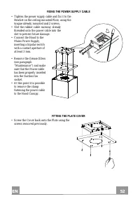
EN 5 52 FIXING THE POWER SUPPLY CABLE • Tighten the power supply cable and fix it to the Bracket on the ceiling mounted Plate, using the tongue already mounted and 2 screws. • Slot the rubber cable raceway already threaded onto the power cable into the slot to prevent future damage. • Connect the Ho...
Page 53 - Control panel
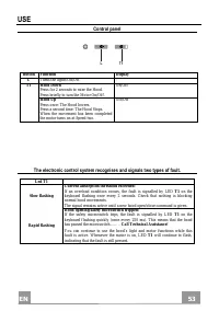
EN 5 53 USE Control panel L T1 Button Function Display L Turns the lights On/Off. - T1 Hood Down Press for 2 seconds to raise the Hood. Press briefly to turn the Motor On/Off. On/Off Hood Up Press once: The Hood lowers. Press a second time: The Hood Stops. When the movement has been completed the mo...
Page 54 - REMOTE CONTROL
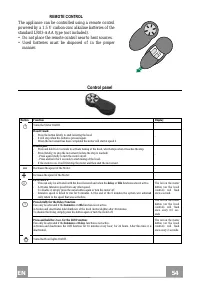
EN 5 54 REMOTE CONTROL The appliance can be controlled using a remote control powered by a 1.5 V carbon-zinc alkaline batteries of the standard LR03-AAA type (not included). • Do not place the remote control near to heat sources. • Used batteries must be disposed of in the proper manner. Control pan...
Page 55 - Grease filter; CLEANING METAL SELF- SUPPORTING GREASE FILTER; Activated Charcoal Filter (Recirculation Version); CHANGING; Lighting unit
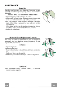
EN 5 55 MAINTENANCE Grease filter The filter must be cleaned every 2 months of operation, or more frequently for particularly heavy usage, and can be washed in a dishwasher. CLEANING METAL SELF- SUPPORTING GREASE FILTER • Open the lighting unit by pulling on the nocth. • Remove the filter one by one...
Page 56 - Check that the four cables are all at the same tension.
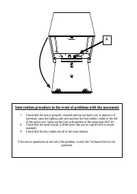
Intervention procedure in the event of problems with the movement 7. Check that the fuse is properly inserted and has not burnt out; to replace it if necessary open the lighting unit and unscrew the fuse holder visible to the left of the motor unit, replacing the fuse with another of the same type (...
Page 57 - FR; CONSEILS ET SUGGESTIONS
FR 5 57 CONSEILS ET SUGGESTIONS Les instructions pour l’utilisation se réfèrent aux différents modèles de cet appareil. Par conséquent, certaines descriptions de caractéristiques particulières pourraient ne pas appartenir spécifiquement à cet appareil. INSTALLATION • En aucun cas le fabricant ne peu...
Page 58 - UTILISATION
FR 5 58 • Si les instructions d’installation du plan de cuisson à gaz spécifient une distance supérieure à celle indiquée ci-dessus, veuillez impérativement en tenir compte. Toutes les normes concernant l’évacuation de l’air doivent être respectées. • Utiliser exclusivement des vis et des petites pi...
Page 59 - les parties accessibles peuvent devenir très chaudes durant; ENTRETIEN; débrancher l’appareil du secteur.
FR 5 59 • ATTENTION : les parties accessibles peuvent devenir très chaudes durant l’utilisation des appareils de cuisson. ENTRETIEN • Avant d’effectuer toute opération de nettoyage et d’entretien, éteindre ou débrancher l’appareil du secteur. • Nettoyer et/ou remplacer les filtres après le délai ind...
Page 60 - CARACTERISTIQUES; Composants
FR 6 60 CARACTERISTIQUES Composants Réf. Q.té Composants du produit 1 1 Corps de hotte équipé de : commandes, lumière, filtres, moteur. 2 1 Plaque support hotte Réf. Q.té Composants de l’installation 11 4 Chevilles ø 10 12a 4 Vis 4,2 x 44,4 Q.té Documentation 1 Manuel d’instructions
Page 61 - Encombrement
Page 62 - Séquence des opérations d’installation; Ouverture de la plaque et préparation à son montage; doit se trouver en face de l’installateur.
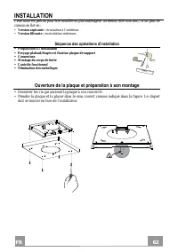
FR 6 62 INSTALLATION Cette hotte est prévue pour être installée au plafond/étagère, au-dessus (650 mm min.) d’un plan de cuisson en îlot en : • Version aspirante : évacuation à l’extérieur. • Version filtrante : recirculation intérieure. Séquence des opérations d’installation • Préparation à l’insta...
Page 63 - Perçage plafond/étagère et fixation plaque; PERÇAGE PLAFOND/ÉTAGÈRE; indiqué dans la figure.
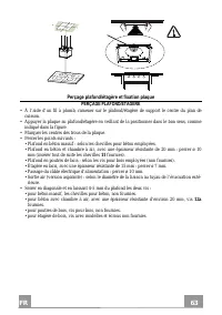
FR 6 63 Perçage plafond/étagère et fixation plaque PERÇAGE PLAFOND/ÉTAGÈRE • À l’aide d’un fil à plomb, ramener sur le plafond/étagère de support le centre du plan de cuisson. • Appuyer la plaque au plafond/étagère en veillant de la positionner dans le bon sens, comme indiqué dans la figure. • Marqu...
Page 64 - FIXATION PLAQUE
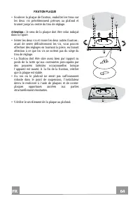
FR 6 64 FIXATION PLAQUE • Soulever la plaque de fixation, emboîter les trous sur les deux vis précédemment prévues au plafond et tourner jusqu’au centre du trou de réglage. Attention : le sens de la plaque doit être celui indiqué dans la figure. • Serrer les deux vis et visser les deux autres fourni...
Page 65 - CONNEXION CÂBLES HOTTE-PLAQUE; d’éviter que le poids de la hotte puisse peser sur la structure.
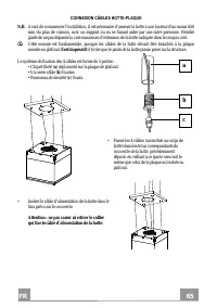
FR 6 65 a b c CONNEXION CÂBLES HOTTE-PLAQUE N.B. Avant de commencer l’installation, il est nécessaire d’amener la hotte à une hauteur d'au moins 650 mm du plan de cuisson, avec un support ou en se faisant aider par une autre personne. Prendre garde de ne pas dépasser la cote maximum d’extension de l...
Page 66 - • Enfiler les pommeaux de sécurité (
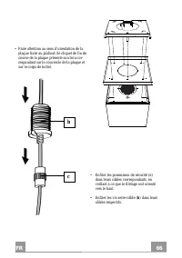
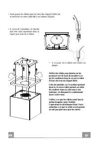
FR 6 66 • Faire attention au sens d’orientation de la plaque fixée au plafond (le cliquet de fin de course de la plaque présente son trou cor-respondant sur le couvercle de la plaque et sur le corps de hotte). • Enfiler les pommeaux de sécurité ( c ) dans leurs câbles correspondants, en veillant à c...
Page 67 - • Faire passer les câbles dans les trous des cliquets filetés (
FR 6 67 • Faire passer les câbles dans les trous des cliquets filetés ( a ) et serrer les vis serre-câble ( b ) à ces mêmes cliquets. • À la fin de l’opération, le résultat doit être celui représenté dans la figure pour tous les 4 câbles. • À ce point, les 4 câbles sont reliés à la plaque. Mettre le...
Page 68 - NIVELLEMENT DE LA HOTTE
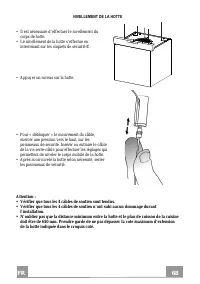
FR 6 68 NIVELLEMENT DE LA HOTTE • Il est nécessaire d’effectuer le nivellement du corps de hotte. • Le nivellement de la hotte s’effectue en intervenant sur les cliquets de sécurité C . • Appuyer un niveau sur la hotte. • Pour « débloquer » le mouvement du câble, exercer une pression vers le haut, s...
Page 69 - Connexions; SORTIE AIR VERSION ASPIRANTE; • Ouvrir le groupe d’éclairage en le tirant sur l’encoche prévue à
FR 6 69 Connexions SORTIE AIR VERSION ASPIRANTE Pour l’installation de la hotte version aspirante, voir les instruc-tions contenues dans le kit d’aspiration spécifique pour la hotte. SORTIE DE L’AIR VERSION FILTRANTE • Ouvrir le groupe d’éclairage en le tirant sur l’encoche prévue à cet effet. • Ret...
Page 70 - FIXATION DU CÂBLE D’ALIMENTATION
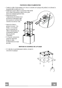
FR 7 70 FIXATION DU CÂBLE D’ALIMENTATION • Tendre le câble d’alimentation et le fixer à la bride sur la plaque de plafond, en utilisant la languette déjà montée avec 2 vis. • Emboîter le passe-câble en caoutchouc déjà enfilé sur le câble d’alimentation dans le trou, pour éviter tout endommagement fu...
Page 71 - Tableau des commandes
FR 7 71 UTILISATION Tableau des commandes L T1 Touche Fonction Affichage L Allume/Éteint les lumières - T1 Hotte basse Appuyer pendant 2 secondes pour remonter la hotte. Appui bref On/Off moteur Branché/Débranché Hotte haute Premier appui : La hotte descend. Deuxième appui : Stop hotte. À la fin du ...
Page 72 - TELECOMMANDE; • Ne pas jeter les piles il faut les déposer dans les ré-
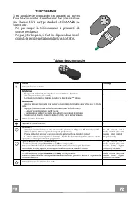
FR 7 72 TELECOMMANDE Il est possible de commander cet appareil au moyen d’une télécommande, alimentée avec des piles alcalines zinc-charbon 1,5 V du type standard LR03-AAA 25 (ne fournis pas). • Ne pas ranger la télécommande à proximité de sources de chaleur. • Ne pas jeter les piles; il faut les dé...
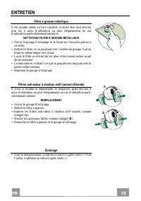
Page 73 - Filtre à graisse métallique; NETTOYAGE FILTRE À GRAISSE MÉTALLIQUE; Éclairage
FR 7 73 ENTRETIEN Filtre à graisse métallique Il est lavable même au lave-vaisselle. Il doive être lavé environ tous les 2 mois d’utilisation ou plus fréquemment en cas d’utilisation particulièrement intensive. NETTOYAGE FILTRE À GRAISSE MÉTALLIQUE • Ouvrir le groupe d’éclairage en le tirant sur l’e...
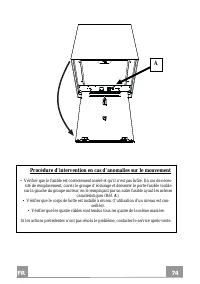
Page 74 - Procédure d’intervention en cas d’anomalies sur le mouvement
FR 7 74 Procédure d’intervention en cas d’anomalies sur le mouvement • Vérifier que le fusible est correctement inséré et qu’il n’est pas brûlé. En cas de néces- sité de remplacement, ouvrir le groupe d’éclairage et desserrer le porte-fusible visible sur la gauche du groupe moteur, en le remplaçant ...
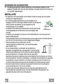
Page 75 - NL; ADVIEZEN EN SUGGESTIES; INSTALLATIE
NL 7 75 ADVIEZEN EN SUGGESTIES De gebruiksaanwijzingen hebben betrekking op verschillende modellen van dit apparaat. Mogelijk vindt u dan ook beschrijvingen van aparte kenmerken die niet over uw specifieke apparaat gaan. INSTALLATIE • De fabrikant is niet aansprakelijk voor eventuele schade als gevo...
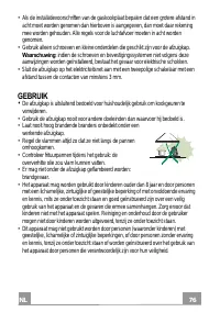
Page 76 - GEBRUIK
NL 7 76 • Als de installatievoorschriften van de gaskookplaat bepalen dat een grotere afstand in acht moet worden genomen dan hierboven is aangegeven, dan moet daar rekening mee worden gehouden. Alle regels voor de luchtafvoer moeten in acht worden genomen. • Gebruik alleen schroeven en kleine onder...
Page 77 - delen erg heet worden ”.; ONDERHOUD; reinigings- of onderhoudswerkzaamheden uit te voeren.
NL 7 77 • “ LET OP : tijdens het gebruik van de kooktoestellen kunnen de toegankelijke delen erg heet worden ”. ONDERHOUD • Schakel het apparaat uit of koppel het los van het elektriciteitsnet alvorens reinigings- of onderhoudswerkzaamheden uit te voeren. • De filters reinigen en/vervangen na de aan...
Page 78 - EIGENSCHAPPEN; Onderdelen
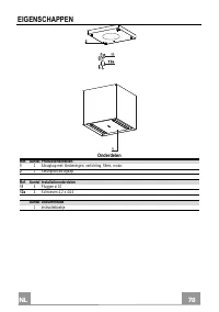
NL 7 78 EIGENSCHAPPEN Onderdelen Ref. Aantal Productonderdelen 1 1 Afzuigkap met: Bedieningen, verlichting, filters, motor. 2 1 Steunplaat afzuigkap. Ref. Aantal Installatieonderdelen 11 4 Pluggen ø 10 12a 4 Schroeven 4,2 x 44,4 Aantal Documentatie 1 Instructieboekje
Page 79 - Buitenafmetingen
Page 80 - Volgorde van de installatiewerkzaamheden; weergegeven. De aanslagpen moet vóór de installateur blijven.
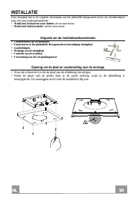
NL 8 80 INSTALLATIE Deze afzuigkap kan in de volgende uitvoeringen aan het plafond/de draagconsole boven een eilandkookplaat (min. 650 mm) worden geïnstalleerd: • Model met luchtafvoer naar buiten: afvoer naar buiten. • Model met luchtcirculatie : interne recirculatie. Volgorde van de installatiewer...
Page 81 - Gaten boren in het plafond/de draagconsole en bevestiging plaat; GATEN BOREN IN HET PLAFOND/DE DRAAGCONSOLE; afbeelding is weergegeven.
NL 8 81 Gaten boren in het plafond/de draagconsole en bevestiging plaat GATEN BOREN IN HET PLAFOND/DE DRAAGCONSOLE • Bepaal met behulp van een paslood het middelpunt van de kookplaat en kruis dit aan op het plafond/de draagconsole. • Zet de plaat tegen het plafond/de draagconsole. Plaats hem in de j...
Page 82 - BEVESTIGING VAN DE PLAAT
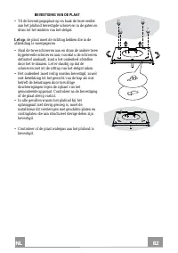
NL 8 82 BEVESTIGING VAN DE PLAAT • Til de bevestigingsplaat op en haak de twee eerder aan het plafond bevestigde schroeven in de gaten en draai tot het midden van het stelgat. Let op : de plaat moet de richting hebben die in de afbeelding is weergegeven • Haal de twee schroeven aan en draai de ander...
Page 83 - AANSLUITING VAN DE KABELS AFZUIGKAP-PLAAT; NB; worden; noodzakelijkerwijs
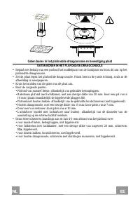
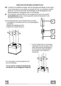
NL 8 83 a b c AANSLUITING VAN DE KABELS AFZUIGKAP-PLAAT NB Voordat u tot installatie overgaat, moet de afzuigkap met behulp van een steun of een tweede persoon op een hoogte van minstens 650 mm van de kookplaat worden gebracht. Let erop de maximale uitschuiflengte van de afzuigkap die in de dimensie...
Page 84 - • Breng de veiligheidsknoppen (
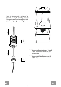
NL 8 84 • Let op de richting van de plaat die aan het plafond is bevestigd (de aanslagpen van de plaat moet samenvallen met een gat op de plaatafdekking en op de afzuigkap). • Breng de veiligheidsknoppen ( c ) op de kabels aan met de schroefdraad naar boven gericht. • Breng de kabelklembouten ( b ) ...
Page 85 - • Voer de kabels door de gleuven van de aanslagpennen met
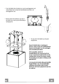
NL 8 85 • Voer de kabels door de gleuven van de aanslagpennen met schroefdraad ( a ) en draai de kabelklembouten ( b ) in de aanslagpennen aan. • Hierna moet het resultaat voor alle 4 de kabels zijn zoals op de afbeelding is weergegeven. • Nu zijn alle 4 de kabels op de plaat aangesloten. Span de ka...
Page 86 - HORIZONTAAL UITLIJNEN VAN DE AFZUIGKAP; behulp van de veiligheidspennen
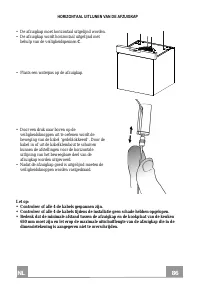
NL 8 86 HORIZONTAAL UITLIJNEN VAN DE AFZUIGKAP • De afzuigkap moet horizontaal uitgelijnd worden. • De afzuigkap wordt horizontaal uitgelijnd met behulp van de veiligheidspennen C . • Plaats een waterpas op de afzuigkap. • Door een druk naar boven op de veiligheidsknoppen uit te oefenen wordt de bew...
Page 87 - Aansluitingen; LUCHTAFVOER MODEL MET LUCHTAFVOER NAAR BUITEN
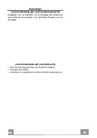
NL 8 87 Aansluitingen LUCHTAFVOER MODEL MET LUCHTAFVOER NAAR BUITEN Raadpleeg voor de installatie van de afzuigkap met luchtafvoer naar buiten de aanwijzingen in de specifieke afzuigset voor de afzuigkap. LUCHTAFVOER MODEL MET LUCHTCIRCULATIE • Open de verlichtingsunit door aan de groef te trekken. ...
Page 88 - BEVESTIGING VAN HET NETSNOER
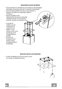
NL 8 88 BEVESTIGING VAN HET NETSNOER • Span het netsnoer en bevestig het aan de beugel op de plafondplaat met behulp van het lipje dat al met 2 schroeven is gemonteerd. • Klem de rubber kabeldoorvoer die al op het netsnoer is geplaatst in de gleuf om toekomstige schade te voorkomen. • Sluit de afzui...
Page 89 - Bedieningspaneel
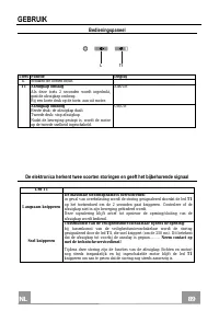
NL 8 89 GEBRUIK Bedieningspaneel L T1 Toets Functie Display L Schakelt de lichten in/uit. - T1 Afzuigkap omlaag Als deze toets 2 seconden wordt ingedrukt, gaat de afzuigkap omhoog. Bij een korte druk op de toets: aan-uit motor. Aan/Uit Afzuigkap omhoog Eerste druk: de afzuigkap daalt. Tweede druk: s...
Page 90 - AFSTANDSBEDIENING; • De batterijen mogen na gebruik niet in het milieu
NL 9 90 AFSTANDSBEDIENING Dit apparaat kan met behulp van een afstandsbediening worden bestuurd. Deze werkt op alkaline zinkkoolstof batterijen van 1,5 V van het standaardtype LR03-AAA (niet inbegrepen). • Bewaar de afstandsbediening niet in de buurt van warmtebronnen. • De batterijen mogen na gebru...
Page 91 - Metalen vetfilter; REINIGEN VAN HET METALEN VETFILTER; Geurfilters met actieve koolstof (Model met luchtcirculatie); VERVANGING; Verlichting
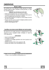
NL 9 91 ONDERHOUD Metalen vetfilter Het vetfilter kan in de vaatwasser worden gewassen en moeten minstens ongeveer iedere 2 maanden worden gewassen, of vaker bij veelvuldig gebruik. REINIGEN VAN HET METALEN VETFILTER • Open de verlichtingsunit door aan de groef te trekken. • Verwijder het filter doo...
Page 92 - Handelingsprocedure bij storingen van de beweging; met de klantenservice.
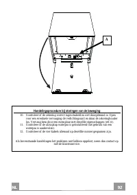
NL 9 92 Handelingsprocedure bij storingen van de beweging 10. Controleer of de zekering correct ingeschakeld en niet doorgebrand is. Open voor een eventuele vervanging de verlichtingsunit en draai de zekeringhouder los. Vervang hem door een exemplaar met dezelfde eigenschappen (ref.A). 11. Controlee...
Page 93 - ES; CONSEJOS Y SUGERENCIAS; INSTALACIÓN; • La distancia mínima de seguridad entre el plano de cocción y
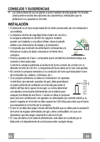
ES 9 93 CONSEJOS Y SUGERENCIAS Las instrucciones de uso se aplican a varios modelos de este aparato. Por lo tanto, usted puede encontrar descripciones de características individuales que no pertenecen a su aparato en concreto. INSTALACIÓN • El fabricante no se hace responsable de los daños provocado...
Page 95 - : las partes accesibles pueden calentarse mucho durante el uso de; MANTENIMIENTO; limpieza o mantenimiento.
ES 9 95 • ATENCIÓN : las partes accesibles pueden calentarse mucho durante el uso de aparatos de cocción. MANTENIMIENTO • Apague o desconecte el aparato de la red eléctrica antes de cualquier operación de limpieza o mantenimiento. • Limpie y/o reemplace los filtros después del período de tiempo espe...
Page 96 - CARACTERÍSTICAS; Componentes
ES 9 96 CARACTERÍSTICAS Componentes Ref. Cant. Componentes de producto 1 1 Cuerpo campana dotado de: mandos, luz, filtros, motor. 2 1 Placa de soporte campana Ref. Cant. Componentes de instalación 11 4 Tacos ø 10 12a 4 Tornillos 4,2 x 44,4 Cant. Documentación 1 Manual de instrucciones
Page 97 - Dimensiones
Page 98 - Secuencia operaciones de instalación; Apertura de la placa y preparación para el montaje; de carrera debe estar en posición frontal respecto al instalador.
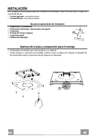
ES 9 98 INSTALACIÓN Esta campana está predispuesta para ser instalada en techo/repisa, sobre (650 mm mín.) un plano de cocción de isla en: • Versión aspirante : evacuación externa. • Versión filtrante : recirculación interna. Secuencia operaciones de instalación • Preparación a la instalación • Perf...
Page 99 - Perforación techo/repisa y fijación placa; PERFORACIÓN TECHO/REPISA; se indica en la figura.
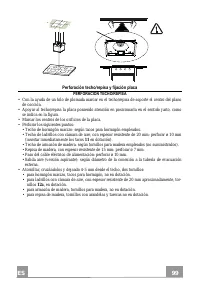
ES 9 99 Perforación techo/repisa y fijación placa PERFORACIÓN TECHO/REPISA • Con la ayuda de un hilo de plomada marcar en el techo/repisa de soporte el centro del plano de cocción. • Apoyar al techo/repisa la placa poniendo atención en posicionarla en el sentido justo, como se indica en la figura. •...
Page 100 - FIJACIÓN DE LA PLACA
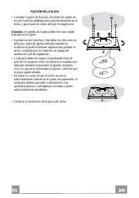
ES 1 100 FIJACIÓN DE LA PLACA • Levantar la placa de fijación, encastrar los ojales en los dos tornillos predispuestos precedentemente en el techo y girar hasta el centro del ojal de regulación. Atención : el sentido de la placa debe ser como aquél indicado en la figura. • Apretar los dos tornillos ...
Page 101 - CONEXIÓN CABLES CAMPANA-PLACA
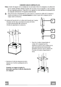
ES 1 101 a b c CONEXIÓN CABLES CAMPANA-PLACA Nota .: Antes de seguir con la instalación es necesario llevar la campana a la altura de por lo menos 650mm desde el plano de cocción con un soporte o con la ayuda de una segunda persona. Atención a no superar la cota máxima de extensión de la campana ind...
Page 102 - • Introducir las perillas de seguridad (
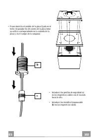
ES 1 102 b c • Poner atención al sentido de la placa fijada en el techo (el pasador fin de carrera de la placa tiene su orificio correspondiente en la cubierta de la placa y en el cuerpo de la campana). • Introducir las perillas de seguridad ( c ) en los respectivos cables con el roscado hacia lo al...
Page 103 - • Pasar los cables por los ojales de los pasadores roscados (
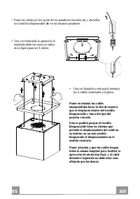
ES 1 103 • Pasar los cables por los ojales de los pasadores roscados ( a ) y atornillar los tornillos bloqueacable ( b ) en los mismos pasadores. • Una vez terminada la operación el resultado debe ser como se indica en la figura para los 4 cables. • Una vez llegados a este punto tenemos los 4 cables...
Page 104 - NIVELACIÓN DE LA CAMPANA; no superar la cota máxima de extensión de la
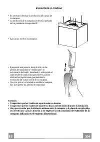
ES 1 104 NIVELACIÓN DE LA CAMPANA • Es necesario efectuar la nivelación del cuerpo de la campana. • La nivelación de la campana se efectúa operando en los pasadores de seguridad C . • Apoyar un nivel en la campana. • Ejerciendo una presión, hacia lo alto, en las perillas de seguridad se “desbloquea”...
Page 105 - Conexiones; SALIDA AIRE VERSIÓN ASPIRANTE; Abrir el grupo iluminación tirándolo en la muesca específica.
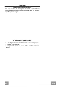
ES 1 105 Conexiones SALIDA AIRE VERSIÓN ASPIRANTE Para la instalación de la campana en versión aspirante tomar como referencia las instrucciones contenidas en el kit aspirante específico para la campana. SALIDA AIRE VERSIÓN FILTRANTE Abrir el grupo iluminación tirándolo en la muesca específica. ...
Page 106 - FIJACIÓN DEL CABLE DE ALIMENTACIÓN
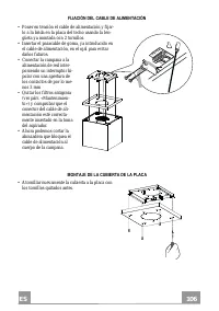
ES 1 106 FIJACIÓN DEL CABLE DE ALIMENTACIÓN • Poner en tensión el cable de alimentación y fijar- lo a la brida en la placa del techo usando la len-güeta ya montada con 2 tornillos. • Insertar el pasacable de goma, ya introducido en el cable de alimentación, en el ojal para evitar daños futuros. • Co...
Page 107 - Tablero de mandos
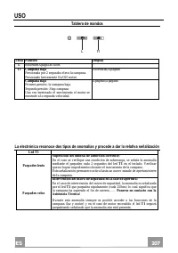
ES 1 107 USO Tablero de mandos L T1 Tecla Función Display L Enciende/Apaga las luces. - T1 Campana baja Presionada por 2 segundos eleva la campana. Presionado brevemente On/Off motor. Encendido/Apagado Campana baja Primera presión: la campana baja. Segunda presión: Stop campana Una vez terminado el ...
Page 108 - MANDO A DISTANCIA; tenedores especiales colocados con dicho fin.
ES 1 108 MANDO A DISTANCIA El aparato puede comandarse con un mando a distancia que funciona con pilas alcalinas zinkcarbón de 1,5 V del tipo standard LR03-AAA (no includo). • No dejar el mando a distancia cerca de una fuente de calor. • Tirar las pilas, cuando se hayan agotado, en los con- tenedore...
Page 109 - Filtro antigrasa metálico; LIMPIEZA FILTRO ANTIGRASA METÁLICO; Filtros antiolor al carbono activo (versión filtrante); SUSTITUCIÓN; Iluminación
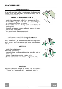
ES 1 109 MANTENIMIENTO Filtro antigrasa metálico Se puede lavar en lavavajillas, y necesita ser lavado almenos cada 2 meses de uso aproximadamente o más frecuentemente, para un uso particularmente intenso. LIMPIEZA FILTRO ANTIGRASA METÁLICO • Abrir el grupo iluminación tirándolo en la muesca específ...